Well Assist User Guide
Overview
Well Assist is an offical FieldTwin application based on Oliasoft’s WellDesign, a well construction engineering suite that works natively in the cloud. When combined with FutureOn's FieldTwin, we offer a class-leading digital twin platform that has proven well engineering capabilities built-in. The impact of field design changes can be immediately modelled in WellDesign, and feedback from WellDesign can be used to optimise the layout and specification of the field.
The Well Assist application currently offers 2 functions:
- Drilling trajectory generation from a known wellhead position
- Automatic (lowest cost) wellhead placement
Getting Started
Create 3D Surfaces
To get maximum benefit out of the integration we recommend that you upload and create layers in FieldTwin Design for the bathymetry and reservoir data you want to use.
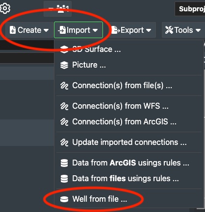
To see an accurate picture of where the wells are positioned in relation to the sea bed and the reservoir, use the Import menu in FieldTwin Design to upload bathymetry and reservoir data.
Create Wells
You can define the well(s) in FieldTwin Design by using the Create menu to create a well manually or the Import menu to import a well from a file.
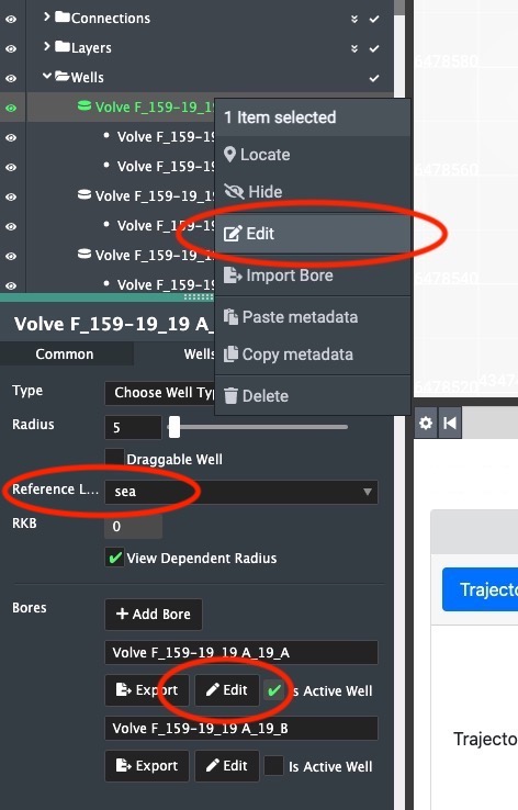
Once the well exists in FieldTwin Design, select it and set its reference level to be sea, sea bed, or RKB. This setting determines how the generated drilling trajectory path will be interpreted in terms of its starting point. Once set, this value will not normally be changed.
Following this, choose Edit from the well's context menu or press a well bore's Edit button.
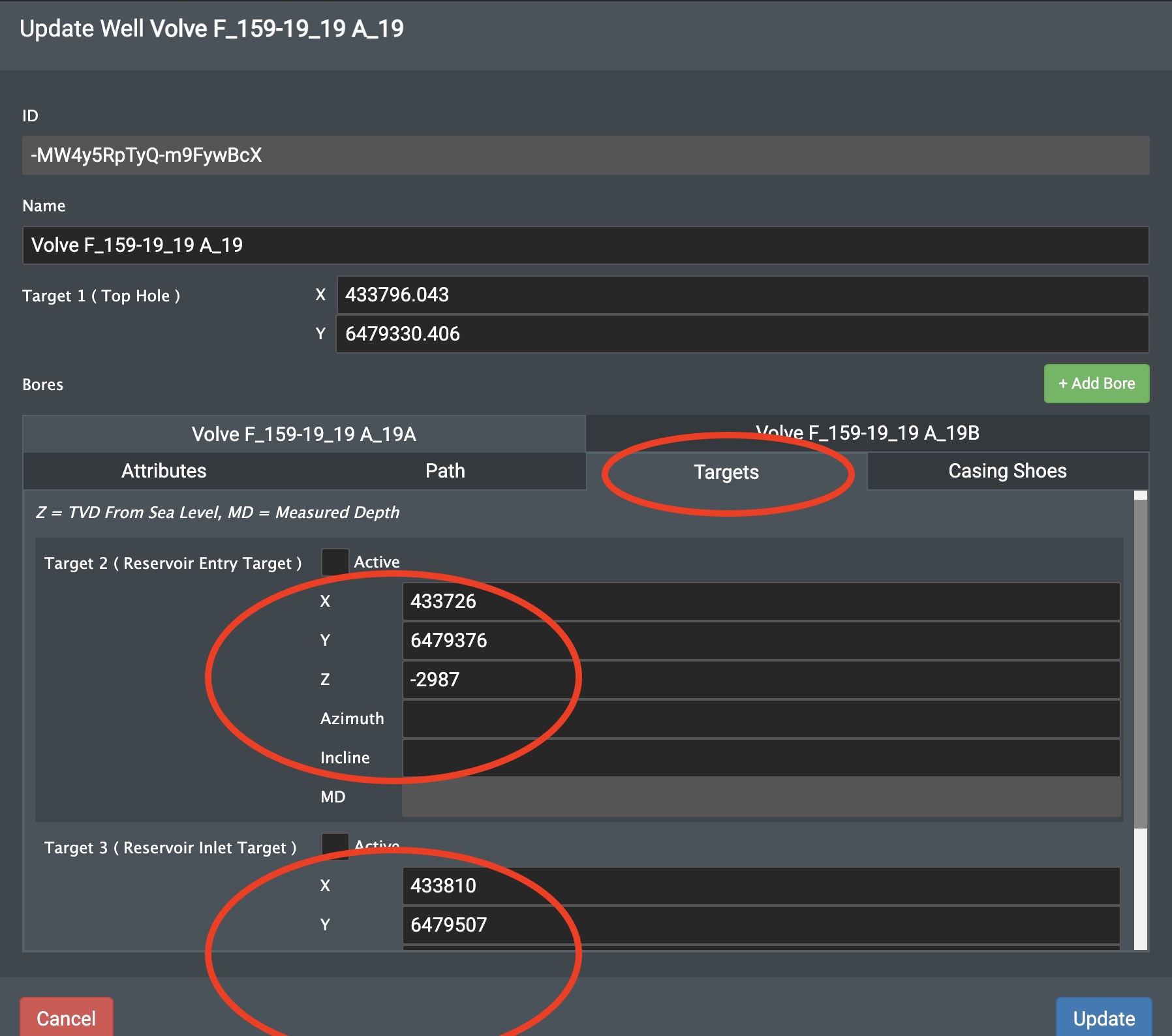
To use the Oliasoft functions requires 2 reservoir targets to be defined for each wellbore. Set the X,Y,Z positions of each target, where Z is always vertical depth from sea level. If you want to run the trajectory generation function you also need to define the azimuth and inclination. The Measured Depth of the targets cannot be set manually, it will be calculated by Oliasoft. The X and Y coordinates must conform to the coordinate reference system (CRS) set for the project.
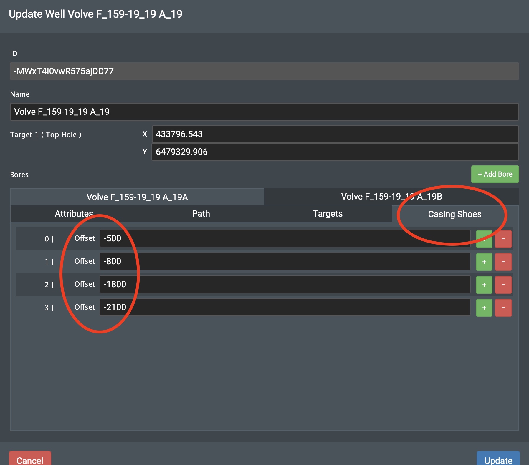
Optionally for the trajectory generation function you can define well casing shoe locations. These are defined as vertical depth from the well's reference level and the casing shoes are shown in the designer in 3D mode.
Switch to 3D view
To see the trajectories generated by Well Assist, switch the designer to 3D mode and navigate below the sea bed to see the well trajectory paths between the sea bed and the reservoir.
You can also open up a second web browser window with the same project to work on the project in both 2D and 3D side-by-side.
Run a Well Assist function
Select the Well Assist tab from the row of tabs in FieldTwin Design, select the well to work with in the designer, then in the Well Assist tab, select the function to perform.
Trajectory Generation
The trajectory generation function will take the top hole location and the wellbore targets defined for the selected well, and calculate the optimal drilling path between these points.
Prerequisites: the well must have at least 1 bore defined. Each bore must have 2 reservoir targets defined. Each target requires X, Y, Z, azimuth, and inclination.
Select the trajectory method. If the method requires any parameters, these will appear below. Then enter a kick-off depth if required, and press the Generate button.
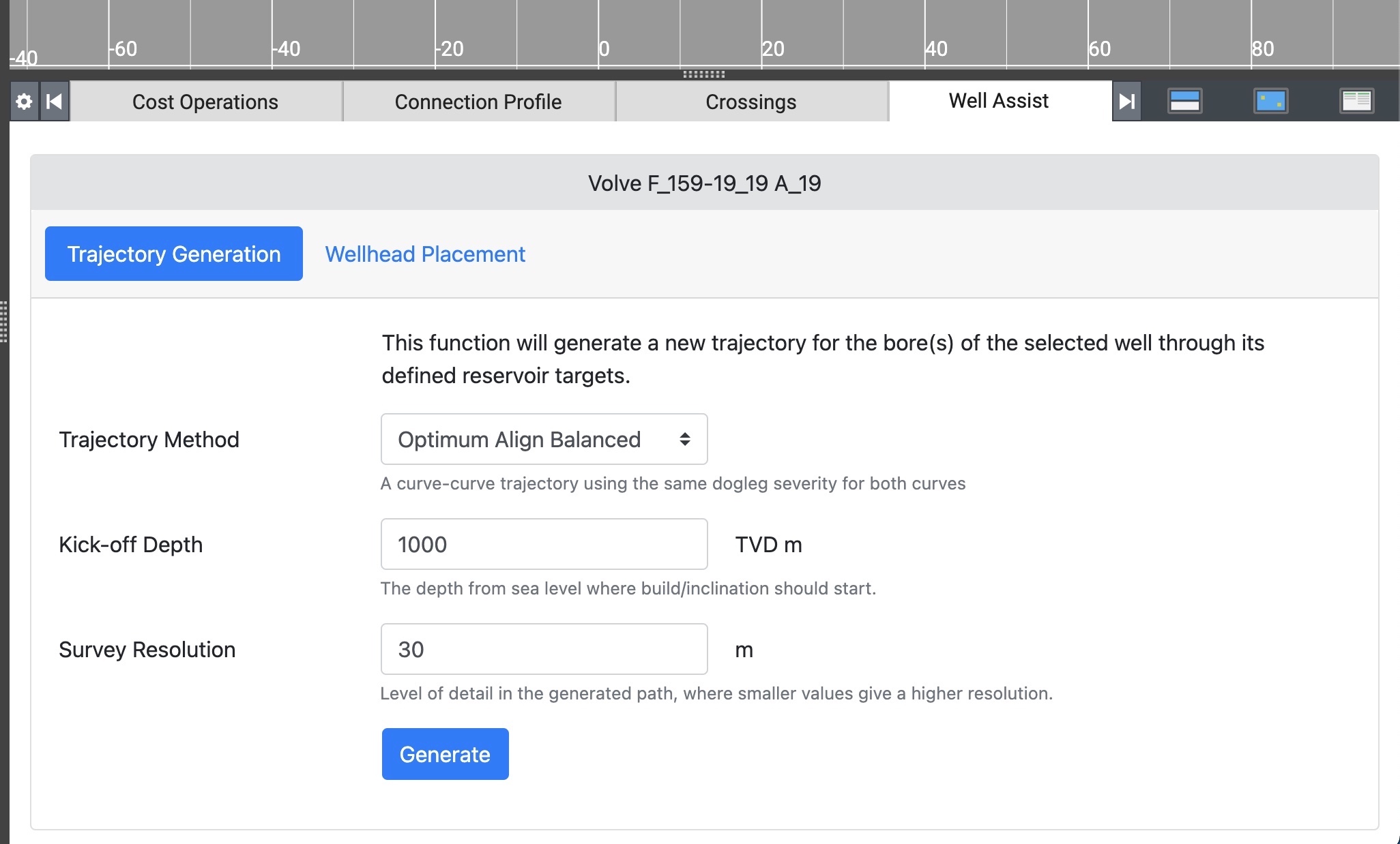
The path is generated as a straight line to the kick-off point, then the selected trajectory method through the remainder of the path to the final reservoir target.
Automatic wellhead placement
The wellhead placement function will take the wellbore targets defined for all the bores of the selected well in FieldTwin Design, and calculate the optimal top hole location. The optimal location is defined by the "lowest cost" found, where the cost metric can be set as a parameter.
Prerequisites: the well must have at least 1 bore defined. Each bore must have 2 reservoir targets defined. Each target requires X, Y, and Z.
Select the trajectory method. If the method requires any parameters, these will appear below. Then enter a kick-off depth if required and the metric to use for cost.
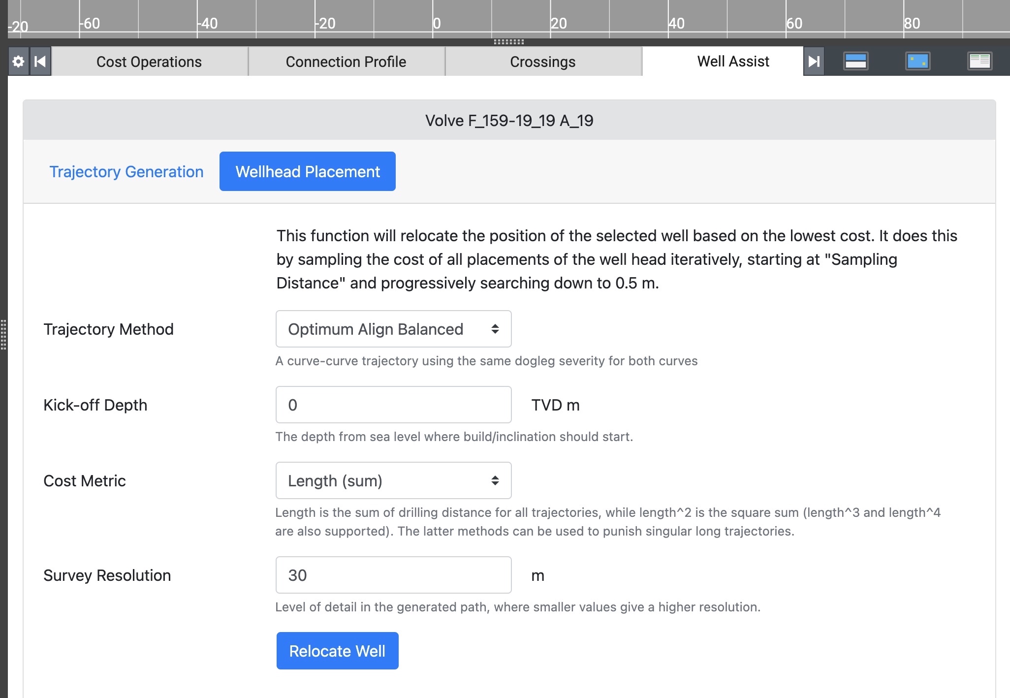
The path is generated as a straight line to the kick-off point, the selected trajectory method to the first reservoir target, and a straight line to the final reservoir target. Warning! This function is mathematically intensive and is known to take a long time.
Viewing the result
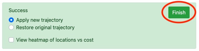
A successful result from Well Assist is indicated by a green box with the new well trajectory applied by default.
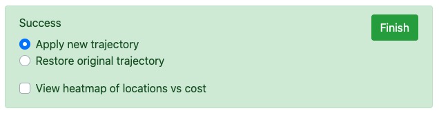
You can toggle between the new trajectory and the original by using the new trajectory and original trajectory radio buttons. It is easiest to see the changes when in 3D view. If you adjust the parameters and run the function again, the toggle shows the latest result or the original (not the previous) trajectory. This is so that you can always roll back the well to its original state.
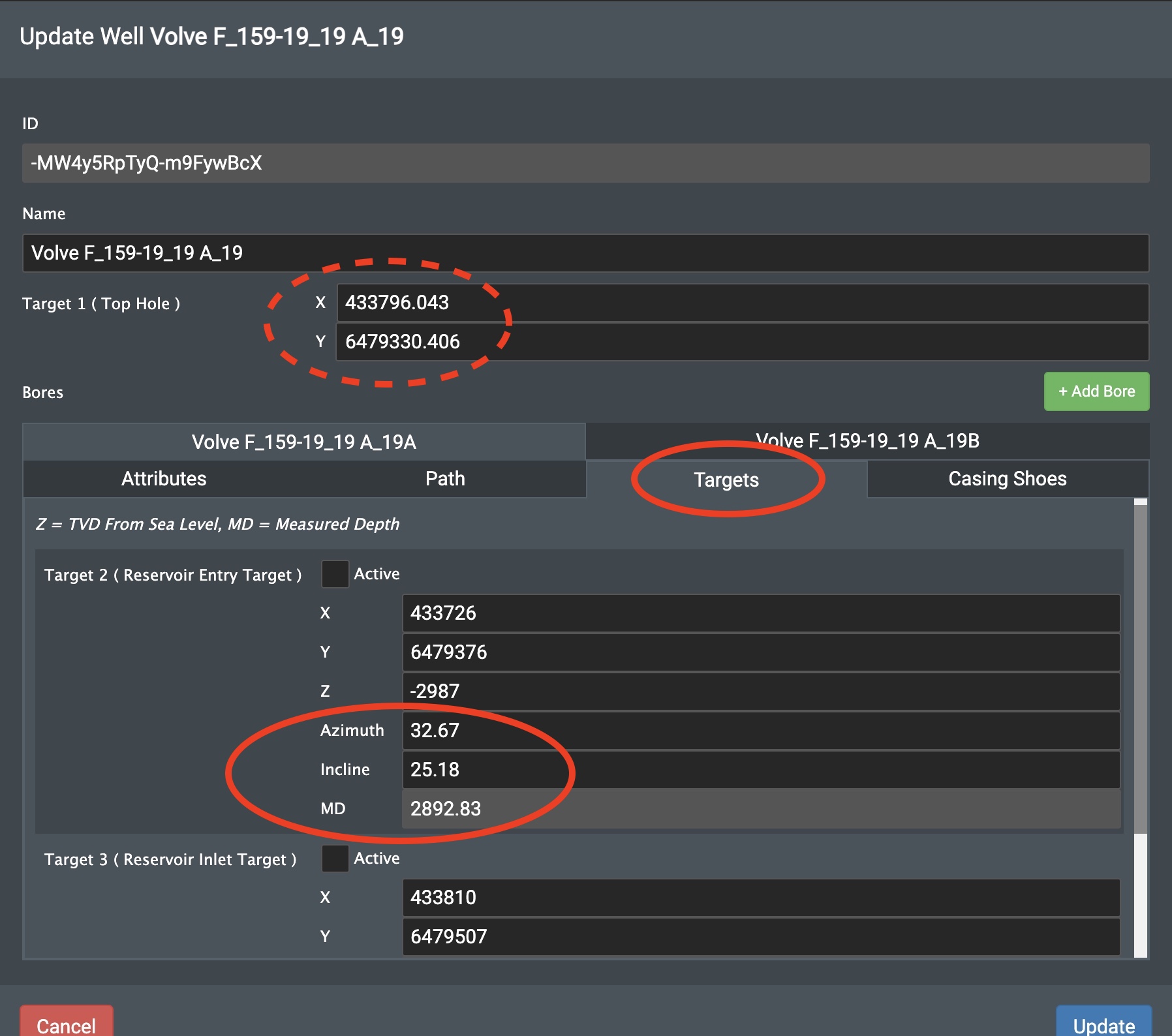
While the new trajectory is applied, you can see the data generated by Well Assist by opening the well edit dialog in FieldTwin Design. Here the calculated trajectory is shown in the Path tab, along with the calculated azimuth, inclination and measured depth. If the survey resolution was set to 30m, the path contains a point for every 30m of its length. Note that the Z and MD values shown here start from the well's defined reference level as described earlier.
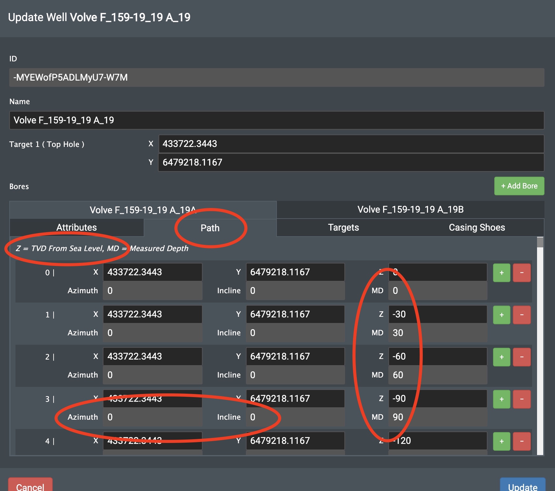
In addition to the trajectory path, the azimuth, inclination and measured depth values of the targets are also updated from the data generated by Well Assist. In the case of the automatic wellhead placement function, the top hole location is updated too.
Click the Finish button to indicate when you are done, before switching function or selecting a different well. Whether the new trajectory is kept or discarded is determined by the final position of the new trajectory or original trajectory toggle button.
Viewing the casing shoe positions
Note! This is for trajectory generation only.
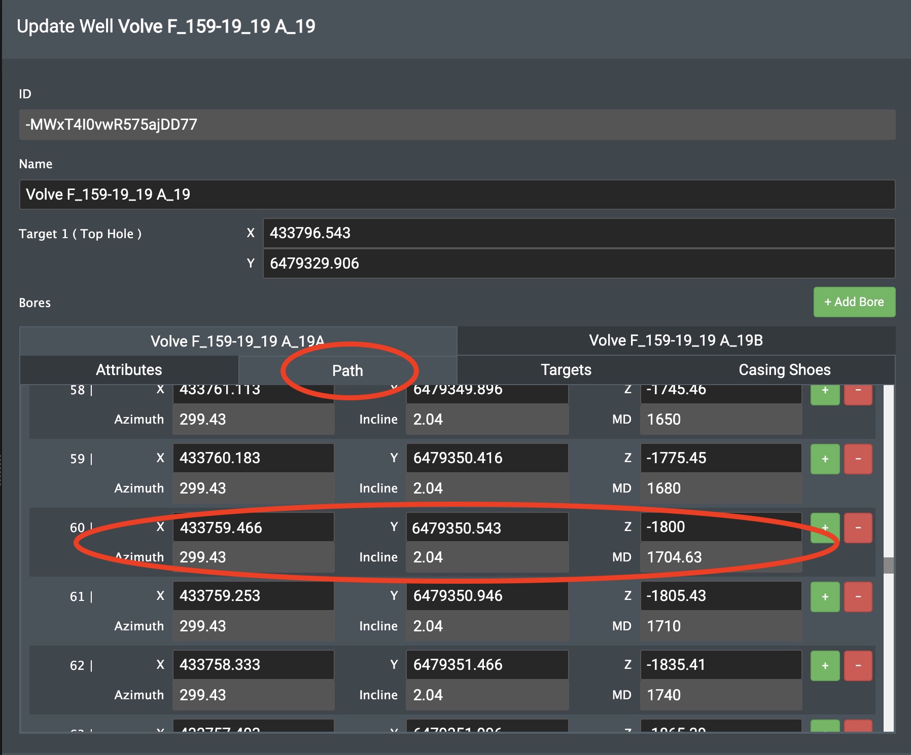
When casing shoes have been defined, the resulting positions (including measured depth, azimuth and inclination) are added to the well bore path and can be looked up from the well's Path tab.
Example result for a casing shoe that was defined at -1800 depth on a well with a reference level of sea:
Viewing the heatmap
Note! This is for wellhead placement only.
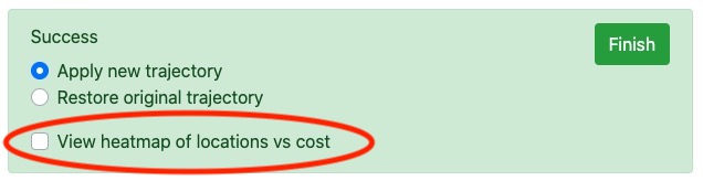
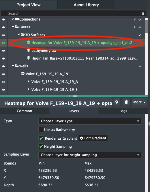
The automatic wellhead placement function provides an optional heatmap to view how the "cost" varies around the optimal top hole location. Enable the View Heatmap checkbox to create a new layer in FieldTwin Design that shows the heatmap.
Once the heatmap layer has been created, it takes up to 30 seconds for the heatmap image to be processed and displayed. The heatmap layer can be removed or left in place. If left in place, running the function again and clicking View Heatmap again will create a second layer. You can delete a heatmap layer at any time by selecting it in the tree view and deleting it from there.
The heatmap is created from the last result generated by Well Assist. It does not matter whether the result toggle is in the new trajectory or original trajectory position.