Wall Thickness Estimator
The FieldTwin Design Wall Thickness module calculates the wall thickness of a rigid (single wall) pipeline/riser/jumper using basic calculations derived from either the API RP 1111 (4th Edition) or DNVGL OS-F101 (2013 Edition) industry guidelines. The wall thickness values provided by the FieldTwin Wall Thickness module only consider the burst and collapse design load cases;
Warning
Please note that the FieldTwin Design Wall Thickness module does not perform ALL of the other design load cases necessary for a complete, accurate, and valid submarine pipeline wall thickness design. This is a pre-engineering module to assist you with quick wall thickness calculations in the concept phase to accelerate and optimize field layout work. You should always do your final wall thickness calculations in your engineering software of choice.
The module estimates two (2) wall thickness values: one that follows a methodology for the burst design load case and another value that uses a methodology for the collapse design load case. The single value returned by the Wall Thickness module will be the larger of these two values. When the user transfers the wall thickness value to the connection's metadata model, only the wall thickness value from one of the two design codes can be selected.
GETTING STARTED
For a complete walkthrough of the Wall Thickness Estimator module, please see the following Tutorial Video
Wall Thickness Estimator: Metadata Requirements
The FieldTwin Design Wall Thickness module uses specific attributes from the Connection’s metadata model as input parameters. If the FieldTwin instance has not adopted FututreOn’s metadata model for the 8 Connection Input parameters required for the Wall Thickness module, it will not function properly. The 8 Connection Input parameters are described in detail in a later section of this document.
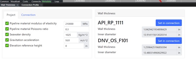
Project Level Input Parameters
The FieldTwin Design Wall Thickness module has several input parameters that are defined at the project level. These Project Level input parameters, with the default values set by FieldTwin, are shown below. Unless there is a compelling reason for changing the default values for the first four (4) parameters [Modulus of Elasticity of the pipeline metal; Poisson’s ratio, Seawater density, or the magnitude of the gravitational acceleration], FutureOn recommends using these default values. The values for Modulus of Elasticity and Poisson’s ratio are typical values for pipeline steel.
The Elevation Reference Height is the location in the pipeline system where the Maximum Design Pressure is specified. It is often above mean sea level (MSL) at a specific location on a platform. The wall thickness calculator assigns this elevation reference height to be at MSL (with a value of 0.0 meter). It must be entered in units of meter, with a positive value showing that the Elevation Reference Height is above the MSL.
Connection Input Parameters
The FieldTwin Design Wall Thickness module also pulls eight (8) input parameters from the selected connection’s metadata model. These eight input parameters, which are shown in the figure below, define the pipeline’s fabrication and function. The parameters are:
- Maximum Design Pressure
- Maximum Design Temperature
- Connection Outer Diameter
- Minimum Internal Pressure
- Pipe Corrosion Allowance
- Pipe Grade (X60, X65, etc.)
- Fabrication Process
- Service (Oil, Gas Injection, Water Injection, etc.)
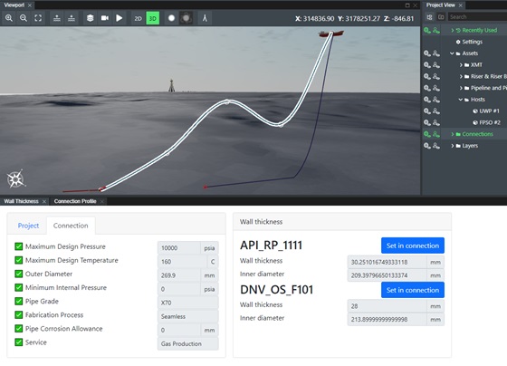
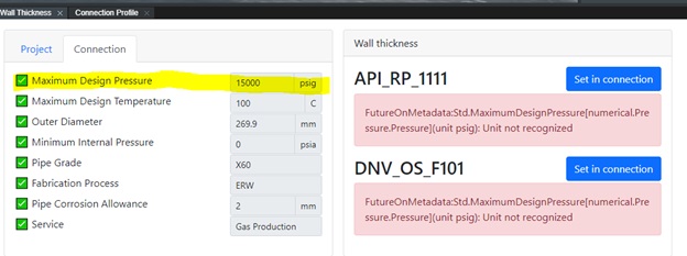
The first 5 parameters require the user to enter numerical values in the connection’s metadata model. The Wall Thickness module prompts the user if the unit used for an input parameters is not supported by the Wall Thickness module. For example, any pressure in psig (gauge pressure) will not work with the module as shown in the figure below.
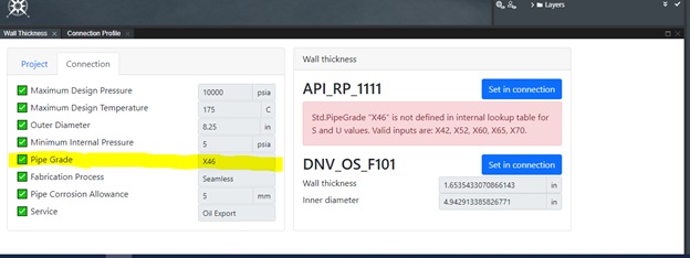
The FutureOn metadata model attributes Pipe Grade, Fabrication Process and Service each have a set of pre-defined values that the user can select from. There are some values that are not compatible with the Wall Thickness Module and selecting one of those values will produce a warning message. An example for Pipe Grade is shown below.
Transferring Wall Thickness Value to Connection
The wall thickness value, and accompanying inner diameter, estimated by the module can be transferred back into the selected Connection’s metadata attributes with the “Set in connection” button in the module. The FutureOn metadata model definition for Wall Thickness and Inner Diameter must be used in the FieldTwin instance for this functionality to work properly. Note the units for the wall thickness and inner diameter will match the unit of measure selected by the user for the outer diameter connection attribute.
Wall Thickness Calculations: Overview
The calculations performed in the Wall Thickness module follow those calculations provided in the API and DNVGL pipeline design guidelines. The module uses the input parameters shown in the interface along with some additional data extracted from the FieldTwin project in the calculations. Both sets of calculations (API and DNVGL) convert all the input parameters to SI units before performing the calculations.
Maximum Water Depth in Connection
The deepest location in the connection is passed into the module and used in calculations. Both the API and DNVGL calculations use this maximum water depth value when estimating the wall thickness needed to meet the collapse (external pressure) design load case. The DNVGL calculations also use the water depth, along with the Elevation reference height value, in the burst design load case.
Pipe Grade Attribute
Both the API and DNVGL guidelines provide instructions on the mapping of the Pipe Grade attribute value to numerical values for the specified minimum yield stress and ultimate tensile strength (Stress) of the steel used in the pipeline. The specified minimum yield stress (SMYS)and specified ultimate tensile strength (SMTS) values are used in the burst and collapse calculations.
Pipeline or Riser Detection
The Wall Thickness module is passed a flag from the FieldTwin backend API to indicate the connection being used by the tool as a riser. That flag is set based on the endpoint connection status, i.e. the connection is attached to a host or rig asset.
Connection “Service” Metadata Attribute
The Wall Thickness module used Connection’s “Service” attribute value to define the density of the fluid inside the connection during operations. The internal fluid density is set automatically by FieldTwin ,and the user cannot change this value. This density is used by the Wall Thickness module only in the DNVGL calculations where it modifies the local internal pressure for the burst design load case.
| Service Attribute | Internal Fluid Density (kg/m3) |
|---|---|
| Oil Production / Oil Export | 750 |
| Water Injection / WAG | 1000 |
| Gas Production / Gas Export / Gas Injection | 200 |
| Meg | 790 |
| Service | 790 |
Fabrication Process
This connection attribute impacts the Wall Thickness module calculation in the collapse design load case. Some fabrication methods, such as ERW, will require more wall thickness to satisfy the collapse design load case.
Maximum Design Temperature
Larger values of this connection attribute cause the Wall Thickness module calculations to estimate higher wall thickness values. Higher Maximum Design Temperature values reduce the value of SMTS and SMYS for each Pipe Grade value.
Water Depth
FieldTwin extracts the relevant water depth data from the Connection and passes it to the Wall Thickness module for the user. The deepest water depth along the connect is used for the collapse design calculations. The water depth will also have an impact on the DNVGL burst design calculations and the Wall Thickness module uses both largest and smallest water depth data for the connection in the calculations.
Seabed depth
Please be aware that when the seabed depth is greater than a 3700m water depth these calculations are no longer valid
Connection Corrosion Allowance
The FieldTwin Wall Thickness module only uses this input data in the DNVGL burst design calculations. If the Wall Thickness module calculates that a larger wall thickness is needed to meet the collapse design case for a connection, there will be no impact seen when changing the Collosion Allowance in the Wall Thickness module.
DNVGL Design Guideline Safety Factors
The calculations from DNVGL use a number of partial safety factors. The value for some of these partial safety factors, such as the
- Material Strength Factor
- Maximum Fabrication Factor
- Material Resistance Factor
can be easily set within the Wall Thickness module. The DNVGL Safety Class Resistance Factor is one that could not easily be set, but it is not presented to the user to define in this release of the Wall Thickness module. For any connection that is not a riser, the DNVGL safety class is Medium. All riser connections are assigned a High safety class in the DNVGL calculations and will therefore typically return a larger wall thickness value from the module than similar “pipeline” connection.
Wall Thickness Estimator Assumptions and Limitations
The most important limitation for the FieldTwin user of this Wall Thickness module is that the pipeline/riser/jumper wall thickness it provides for rigid, single wall connections is just an estimate and does not represent a complete, verified subsea pipeline wall thickness design. Below are additional assumptions and limitations present in the Wall Thickness module:
- Only the burst and collapse design load case conditions are considered; therefore, the wall thickness values provided by the module are only estimated values.
- The module only works for FieldTwin connection with the data attributes Line Type=Rigid and Pipeline Type = Single
- The Wall Thickness module cannot be used with pipe-in-pipe connections.
- DNV guidelines do not provide a clear temperature impact on wall thickness above 200 C. The module assumes a constant derating slope of 40 MPa/100 C when the Maximum Design Temperature is above 200 C
- All riser type connections are assigned a DNVGL safety classification of High. This will result in the module giving generally higher wall thickness values using the DNVGL calculations.
- All pipeline and jumper connections are assigned a DNVGL safety classification of Medium.
- The pipe corrosion allowance data is only used in the DNVGL calculations; it is not used in the API calculations and will not impact those API wall thickness estimates.
- Only the DNVGL burst design load case uses the corrosion allowance in calculating the wall thickness value; therefore, the wall thickness values estimated by the module will not be impacted by this corrosion allowance value when the collapse design load case governs the DNVGL wall thickness estimate. This typically happens with pipelines with a larger outer diameter in deeper water.
Wall Thickness Tutorial
See the video tutorial below for a complete walkthrough of how to use the Wall Thickness Estimator and understand the prerequisites and also any limitations.