OLGA Integration User Guide
Overview
The OLGA integration provides a method for defining "flowpaths" in FieldTwin Design (FT Design) that can be imported into Schlumberger's OLGA application for analysis and flow simulation.
A flowpath consists of 2 or more field objects (staged assets or wells) connected together. A typical flowpath might consist of all the oil production lines between a well and a topside vessel.
The analysis in OLGA is only concerned with the well bores and the connections (pipelines) in the flowpath. OLGA version 2021.1.0, 2021.2.0 or newer is required.
Getting started
Define metadata for connections and wells
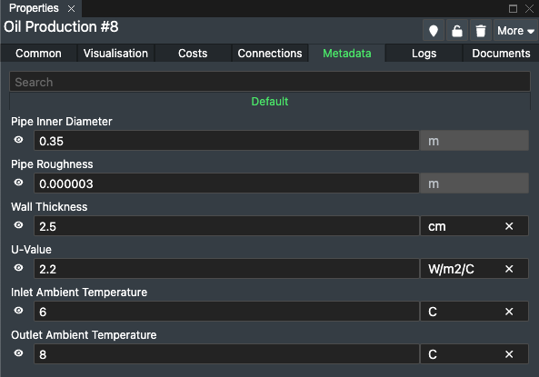
OLGA is able to accept values for pipe Roughness, Internal Diameter, Wall Thickness, U-Value, Inlet Ambient Temperature and Outlet Ambient Temperature. If some or all of these are required, they should be set up as metadata fields by an administrator in FieldTwin (a one-off procedure) and the values entered for each of the wells and the flowlines in the FieldTwin project.
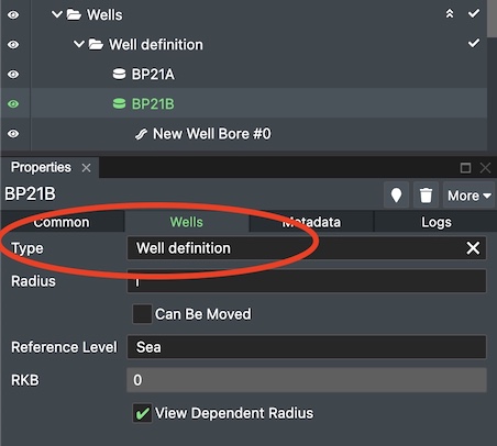
To enter metadata for a well or a well bore you first need to assign a Well Type (or for a bore, a Well Bore Type).
For wells, this metadata can be provided either for the well itself or for an individual well bore. If present in both places then the values for the active bore take precedence.
Link assets to wells
FieldTwin does not allow connections to be directly attached to a well, but rather with an interfacing asset such as a template or a christmas tree. For a well to appear in a flowpath, it must be linked with its corresponding asset.
Linking a christmas tree to a well
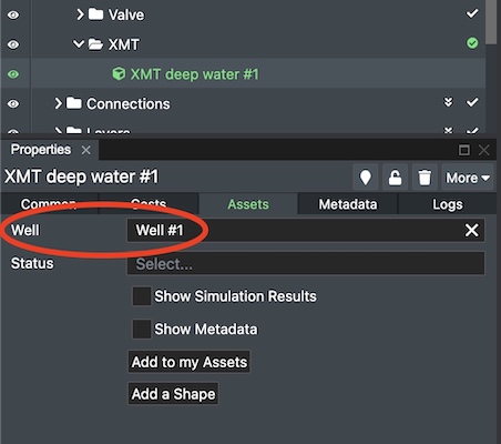
Tree assets in FieldTwin automatically have a Well attribute that must be set as required.
Linking a template to its wells
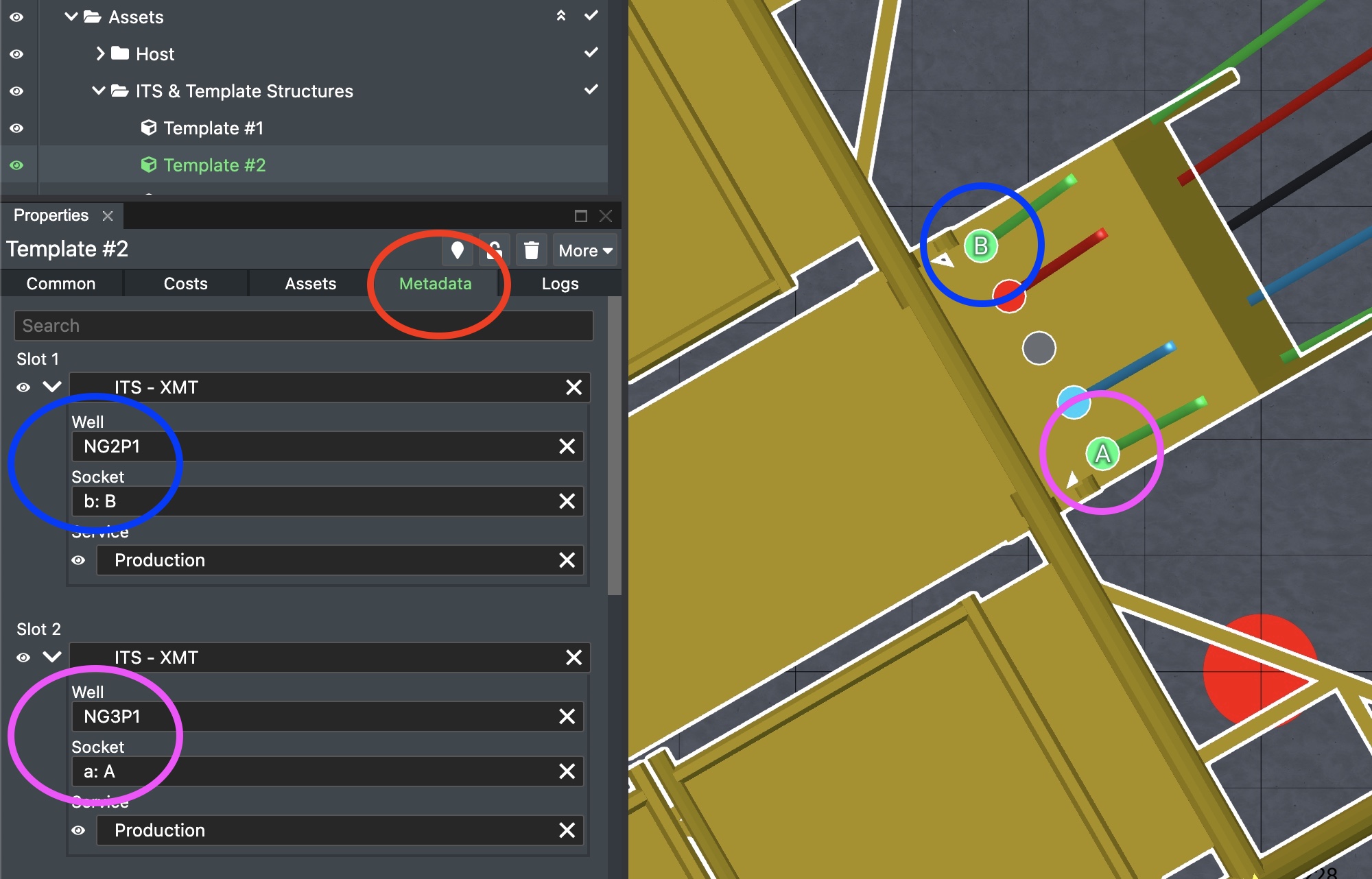
Because a template has several "slots", it may link to several wells. This requires metadata fields to be set up by an administrator in FieldTwin (a one-off procedure), one for each slot in the template. Each slot should be of type Asset, with the asset category set as XMT. The asset type can be a virtual asset if no physical tree is present in the model.
Once this has been set up, you can assign each slot to a well, along with the related connection point in the template.
Define routes through assets
For an asset such as a template or manifold there can be many possible entry and exit points, with internal piping and routing that is specific to that asset. To model the internal routing in FieldTwin so that a flowpath can "follow" it correctly, label the connection points on the asset.
Find the asset in FT Design then press the Edit Connection Points button on the main toolbar. Select the entry point of a route and label it, for example "A". Then select the route's exit point and label it with the same value "A". For the next route, label the entry and exit points "B", and so on.
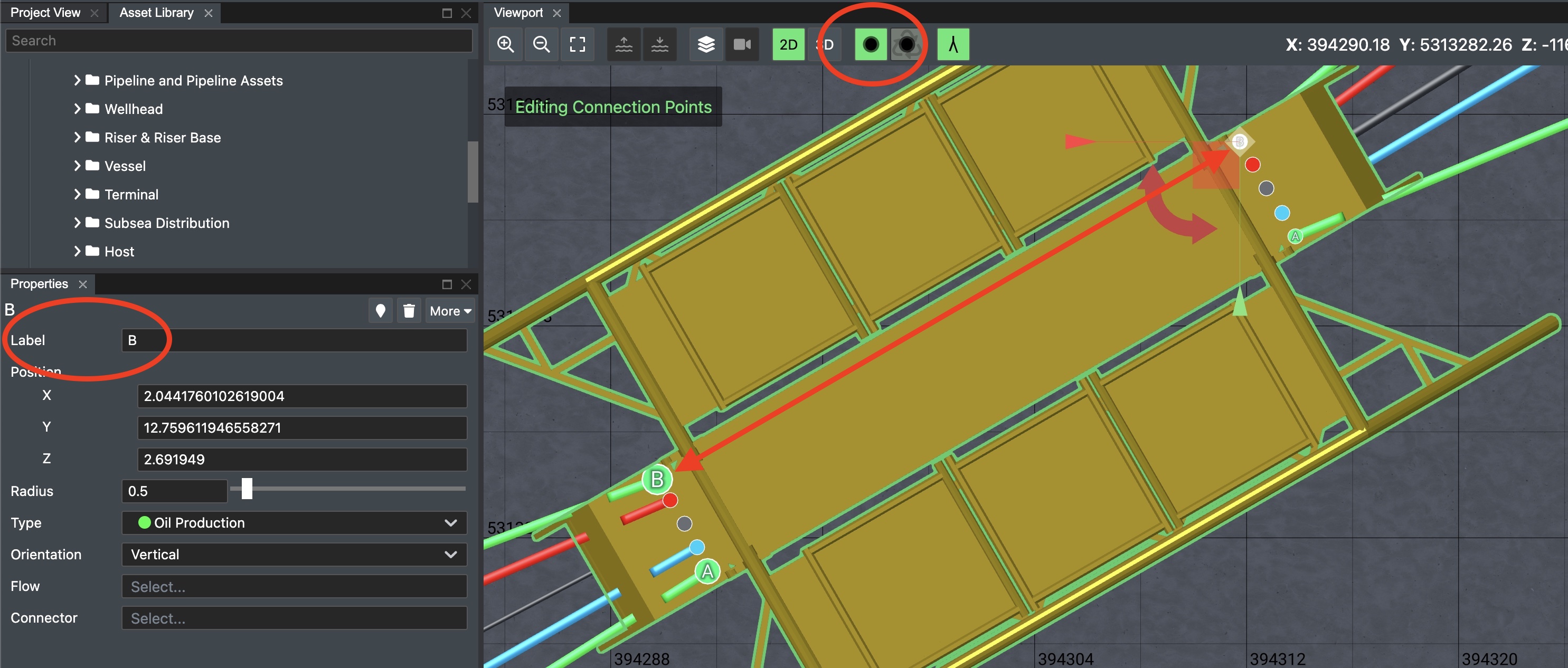
This step is only required for assets where the routing is ambiguous. In the above example, because 2 green oil production lines enter the template, and 2 leave. The other routes are known because there is only one route of each type.
Using the integration
Start by selecting the "OLGA" tab in the bottom row of tabs in FT Design. If it is not shown, press the Layout button and select it to show it.
The integration operates on a per-subproject basis, so the following procedure applies each time you switch project or subproject.
Flowpath search
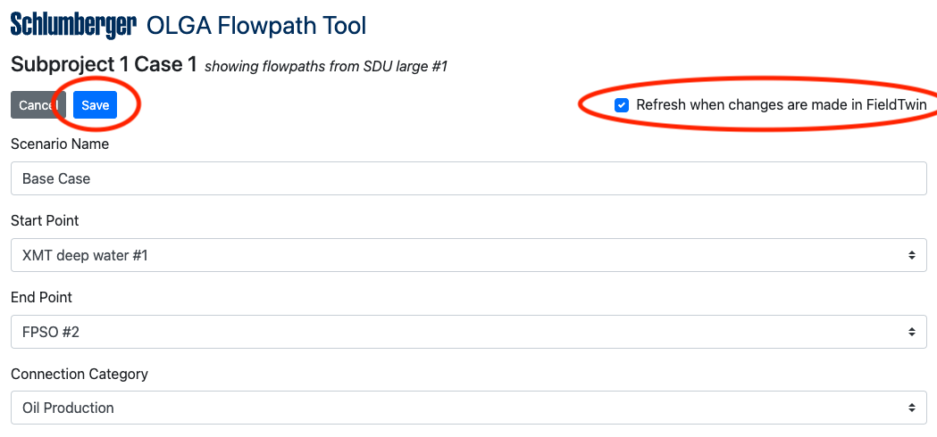
In the OLGA tab, select a starting point for the flowpath search, optionally select an end point, and optionally limit the flowpath to a particular connection type. If these options are hidden, press the Edit button below the description of the current search.
Once the values are set, press Save.
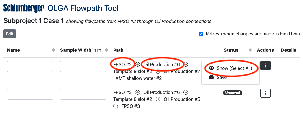
After the flowpath search has completed the list of possible flowpaths will be shown. Saved flowpaths (if any) will be shown at the top, with unsaved flowpaths listed below. To work with a flowpath in OLGA you first need to save it.
Use the Refresh checkbox if you wish to automatically update the list of possible flowpaths as you make changes to the field in FT Design.
For each flowpath in the results list you can find an individual element by clicking on its name, or you can show the whole flowpath by choosing Select All from the flowpath's Actions menu.
Saving and trimming a flowpath
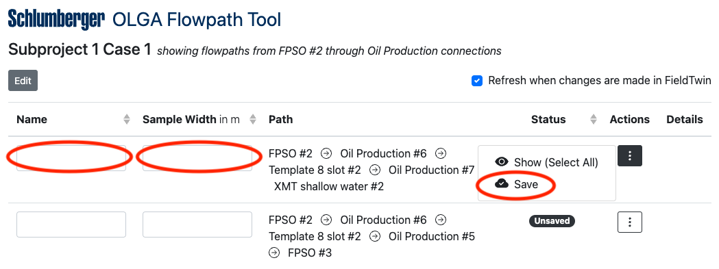
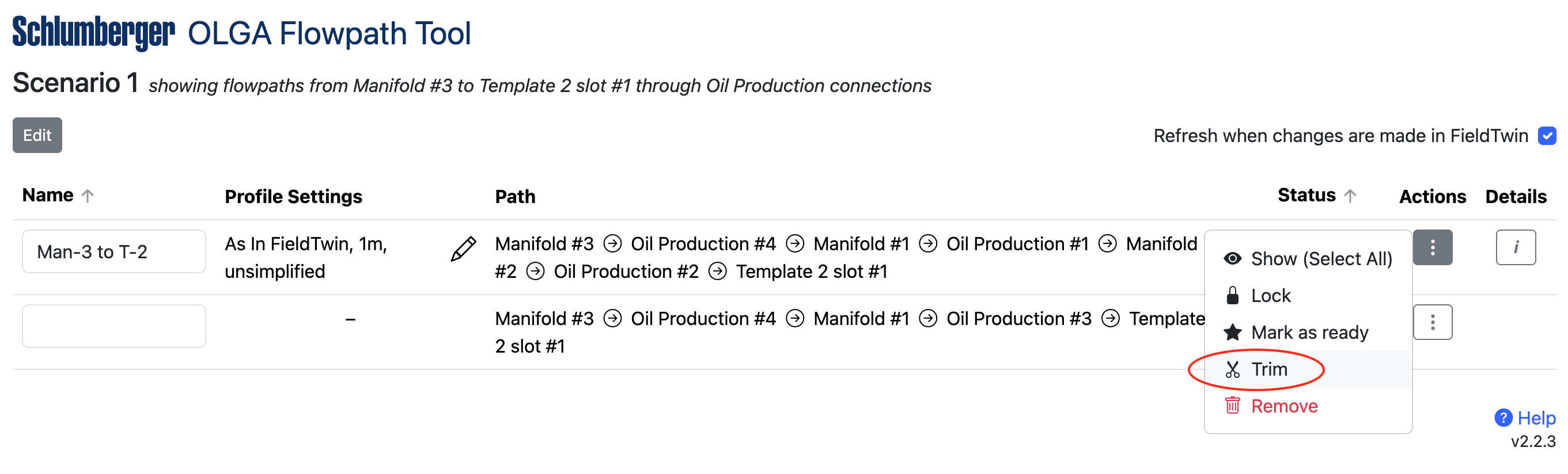
To save a flowpath, enter a name in its text box and choose Save from the flowpath's Actions menu.
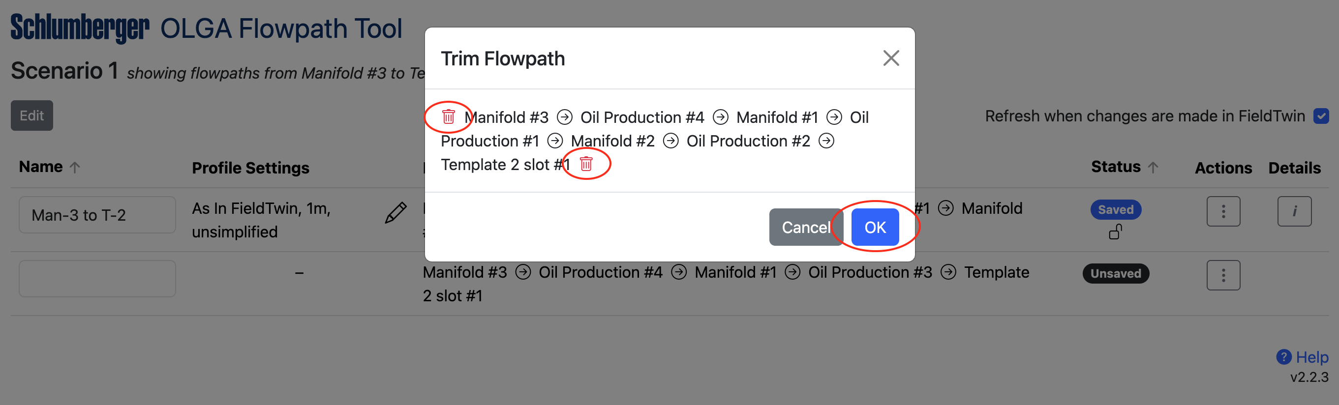
If you want to work with a subset of the whole flowpath, choose Trim from the flowpath's Actions menu. This will give you the ability to trim the flowpath from either end. Press OK to save the trimmed path or Cancel to discard the changes.
Optionally you can lock all of the staged assets and connections in the flowpath to prevent another user from making changes to the flowpath objects while you are working. To do this, press Lock from the flowpath's Actions menu. Once locked, the menu item changes to allow you to Unlock.
Setting the export options for a flowpath
A flowpath may consist of 2 distinct types of connection:
- Connections that were manually drawn or designed in FieldTwin
- These have a Design Type of None or Jumper or Riser or similar in the Properties panel
- For these connections FieldTwin generates a connection profile by joining up the start and end and mid points and placing the connection on top of the bathymetry layer (excluding the floating portion of a riser)
- Connections that were imported via FieldTwin's Import menu, or through the Rules Engine or the API or the Span Estimation Tool
- These have a Design Type of Imported in the Properties panel
- For these connections FieldTwin can either use the imported XYZ data or it can generate a connection profile the same as above
By default, the integration provides OLGA with:
- A generated profile as described above for manually designed connections, with regularly spaced points (every 1 m or foot by default)
- The imported XYZ data for imported connections, where Z depends on the Connection Follows Bathymetry option that was given at import time
- No simplification
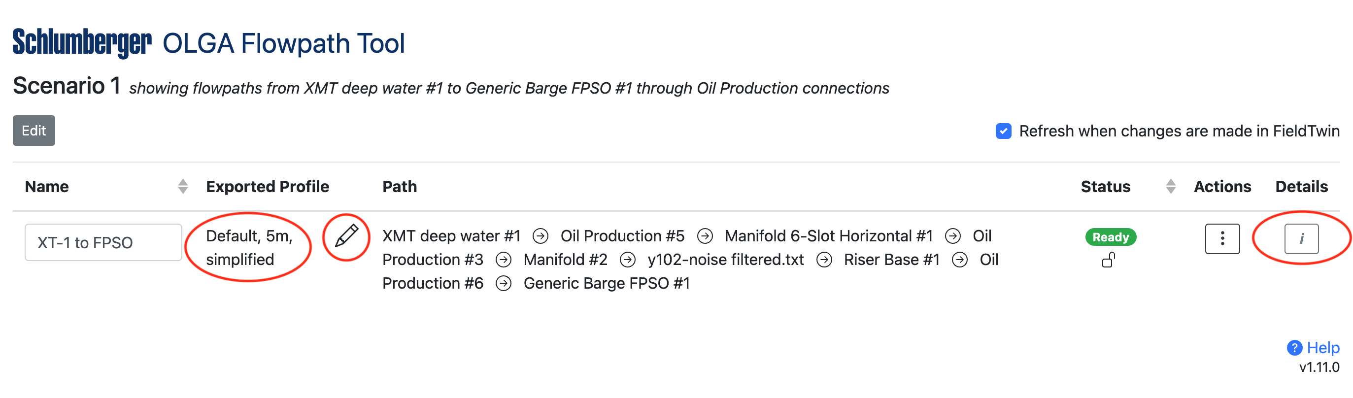
You can change these defaults by pressing the edit (pencil) icon next to a profile description in the flowpaths list.
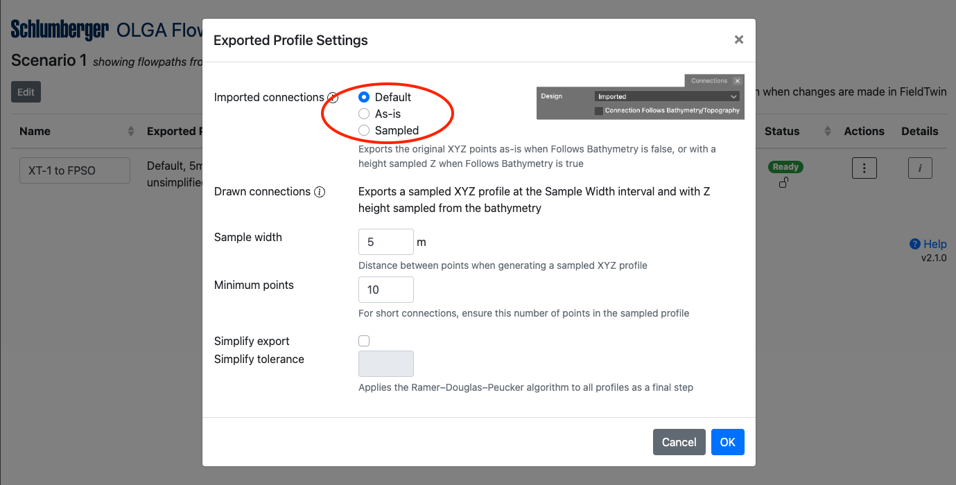
The available options for imported connections are:
| As in FieldTwin | Sampled |
|---|---|
| Uses the imported points in combination with the Connection follows bathymetry connection attribute | Generates a new profile (by interpolating the original XYZ points) using the same method and settings as for 'designed' connections |
| If the connection does not follow the bathymetry, provides the imported XYZ points unchanged | |
| If the connection does follow the bathymetry, replaces the Z component with the depth from FieldTwin's bathymetry layer |
There are no equivalent options for 'designed' connections, since only a small number of user defined geometry points are available in FieldTwin.
The Sample Width setting controls the interval of generated points for 'designed' connections
and for the Sampled option. The lower the value (minimum 1) the more points and the higher
the resolution of the flowpath profile that is made available to OLGA.
Typically you might set this to be the same resolution as the bathymetry under the pipelines.
Depending on the value of Sample Width it is possible that short connections would be exported with a very small number of points. The Minimum Points setting ensures a minimum number of points in the exported profile [* see below], overriding Sample Width when required.
You can optionally simplify the exported profiles to reduce the number of points by
removing points that fall in a straight line. This function uses the
Ramer–Douglas–Peucker algorithm
when enabled. The lower the tolerance (minimum 0.01) the fewer points are removed.
Simplification applies to all profile types for both 'designed' and imported connections.
* As simplification happens last it is possible that a simplified profile will contain fewer points than the Minimum Points setting.
Press OK to save your changes or Cancel to discard them.
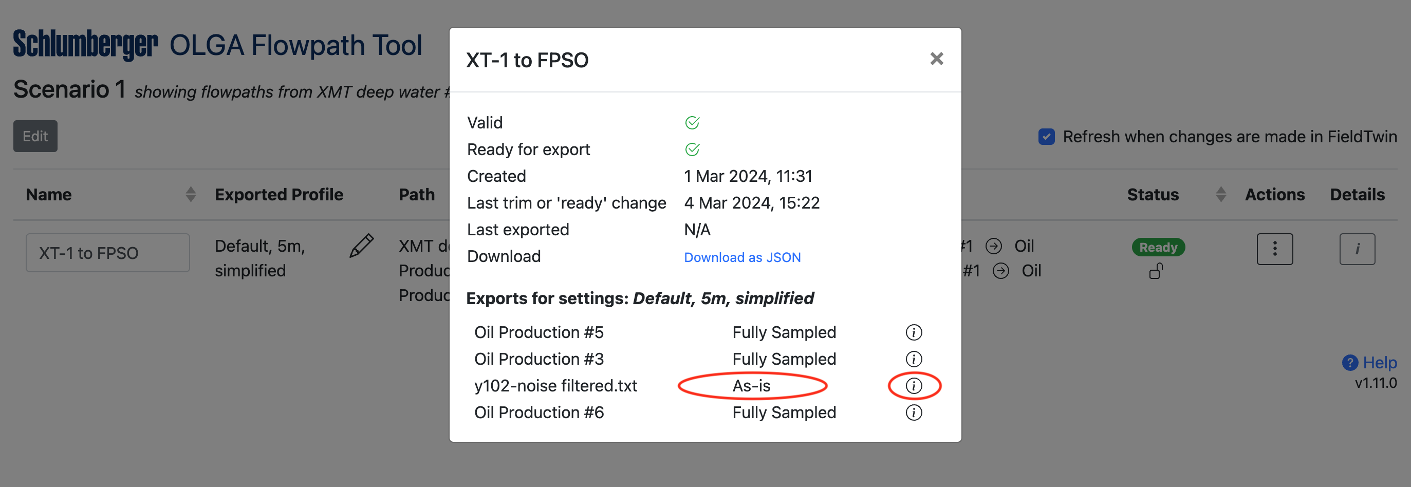
To see the list of connections in a flowpath and what type of profile will be exported for each, return to the main flowpath list and click the flowpath's Details button. In the list of connections you can hover over the "i" icon to see the reason why that profile type applies.
Marking a flowpath as ready for OLGA
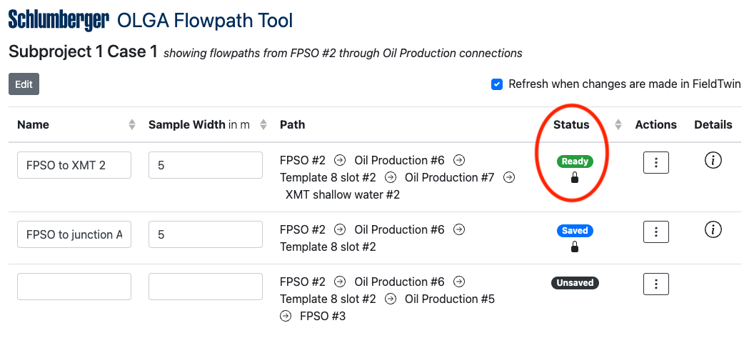
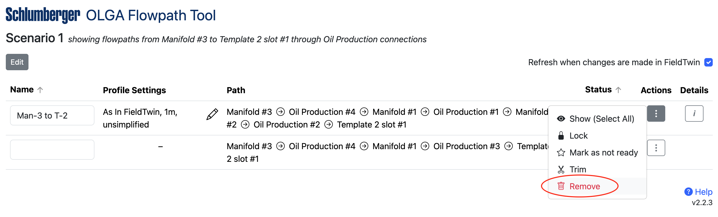
When you are ready to use the flowpath in OLGA, choose Mark as ready from the flowpath's Actions menu. The flowpath's status will be shown in green if it passes all checks, and you can switch to the OLGA application to continue.
A ready flowpath can be moved back to the saved status by choosing Mark as not ready from the flowpath's Actions menu.
Unsaving a flowpath
To remove a flowpath from the list of saved flowpaths, choose Remove from the flowpath's Actions menu.
None of the staged assets or connections in the flowpath are affected by this action. If the removed flowpath matches the current search criteria it will reappear in the list of unsaved flowpaths.
Correcting flowpath problems
Some saved flowpaths may display a yellow or a red status message.
- Status Invalid - this indicates that the field layout has changed since the flowpath was saved and the flowpath now references deleted or reordered elements. Hover over the status message to view the problem. You may be able to remove a deleted element by using the Trim function, otherwise remove the invalid flowpath by choosing Remove from the flowpath's Actions menu. Check the list of unsaved flowpaths for a replacement path that reflects the latest field layout.
- Status Missing Value - this indicates that the flowpath is missing a name or a value for sample width. Hover over the status message to view the problem. A flowpath must have these values set before it can be marked as ready.
- Status Needs Metadata - this indicates that one or more wells or connections in the flowpath is missing a required metadata value (for example roughness or internal diameter) or unit. Hover over the status message to view the problem. Correct this by clicking on a well or connection in the flowpath to select it, then select the Metadata tab in Properties in FT Design and fill in the missing value or unit.
- Status Needs Well Data - this indicates that a well in the flowpath does not have a trajectory defined. Correct this by selecting the well and choosing Edit from its context menu. Create a bore and set its Path, or use the Add Bore From File function, or use FutureOn's Well Assist integration to create a realistic path.
After correcting a problem, use the Refresh button in the integration to update the statuses of the saved flowpaths.
Saved flowpaths with a green Ready status can be imported from OLGA straight away. Switch to the OLGA application to continue.
Flowpaths containing a well
For a flowpath that includes a well, the following 3 scenarios are possible:
- If the flowpath begins with a well, the trajectory of the well's active bore is provided to OLGA, starting from the bottom hole and going up
- If the flowpath ends with a well, the trajectory of the well's active bore is provided to OLGA, starting from the top hole and going down
- If the well is in the middle of a flowpath, it is skipped and not followed
If you do not want to supply the well bore to OLGA, trim the flowpath to remove the well so that the flowpath begins or ends with the well's connecting asset (tree or template) instead.
Continuing in OLGA
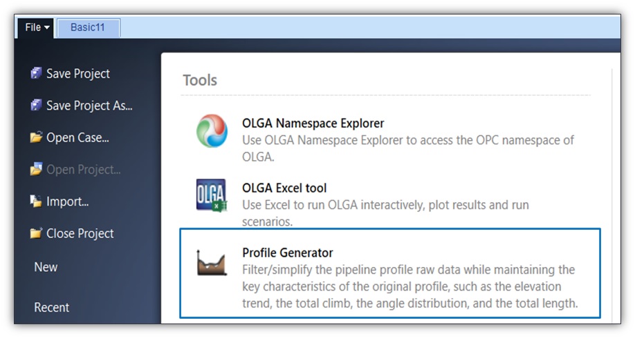
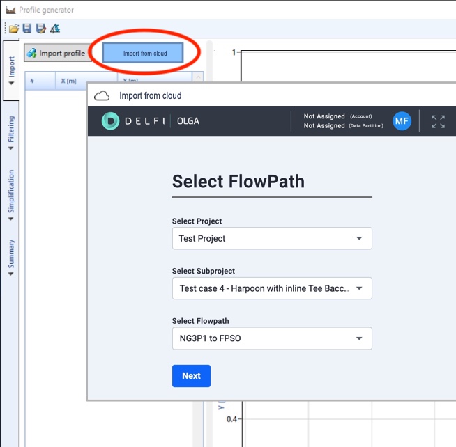
First you need to be in the Olga Profile Generator Tool as shown below:
In OLGA, you can import flowpaths from FieldTwin using OLGA's Import from Cloud function.
To use the import function you need to have a FieldTwin user account registered with the same email address as your Schlumberger DELFI account, but you do not need to have FT Design open.
The first time around, the import will ask you to log in using your DELFI credentials. Once this is done, you will be able to select a FieldTwin project, subproject, and saved Ready flowpath without leaving OLGA.
From here you can analyse the flowpath from your OLGA project. If you make changes to the layout of the path in FT Design, you will need to import it into OLGA again to bring in those changes.
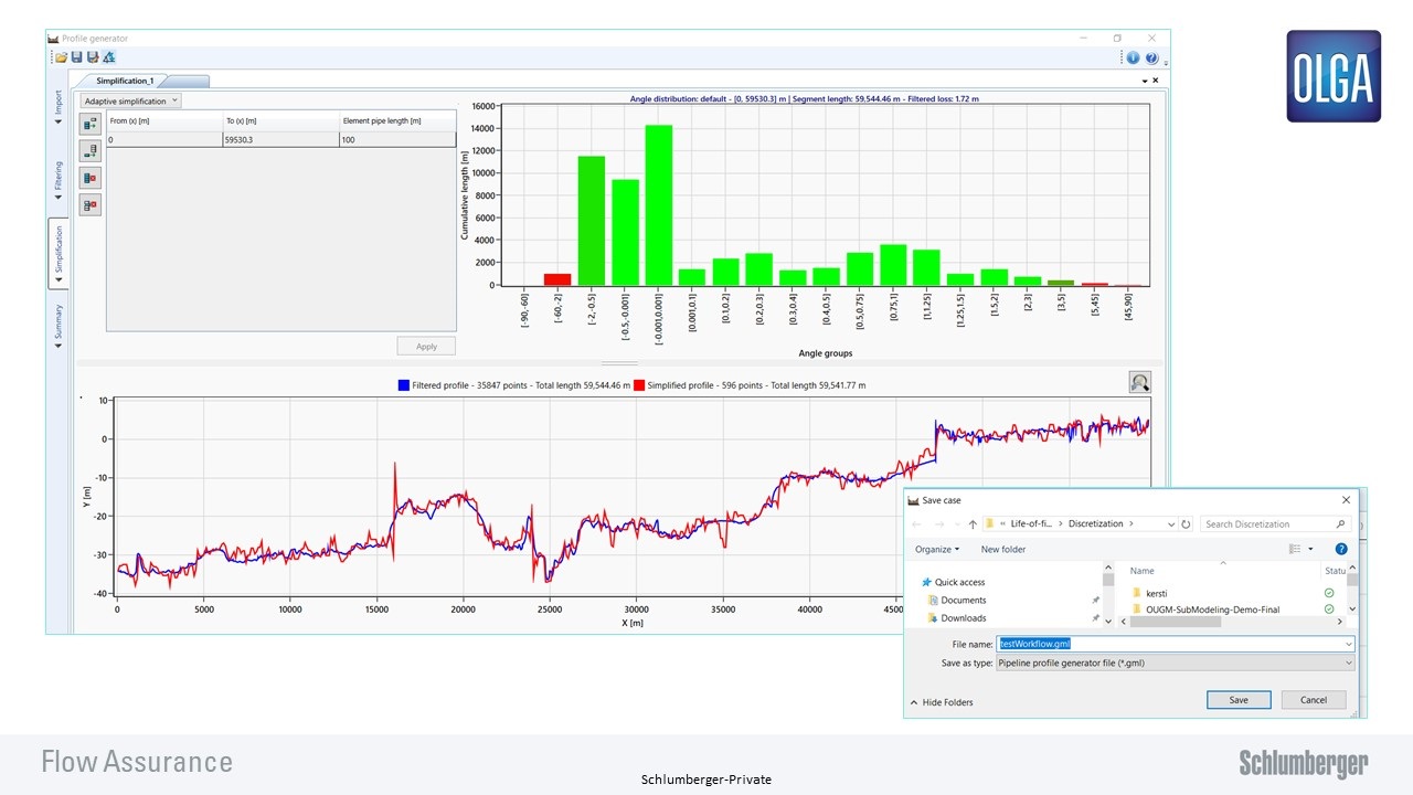
Now you can leverage simplification and filtering options in OLGA.