LedaFlow Integration User Guide
Overview
The LedaFlow integration provides a method for defining "flow paths" in FieldTwin Design (FT Design) that can be imported into Kongsberg Digital's LedaFlow application for analysis and flow simulation.
A flow path consists of 2 or more field objects (staged assets or wells) connected together. A typical flow path might consist of all the oil production lines between a well and a topside vessel.
The first release of this integration only supports connections (pipelines) in a flow path. It is planned to add support for wells at a later date.
Getting started
Define metadata for connections
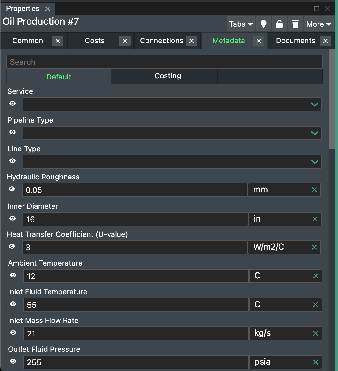
LedaFlow requires values for pipe Ambient Temperature, U-Value, Inner Diameter and Roughness. In addition, the inlet connection requires Fluid Temperature and Mass Flow Rate. The outlet connection requires Fluid Pressure.
These must be set up as metadata fields by an administrator in FieldTwin (a one-off procedure) and the values entered for each of the flow lines in the FieldTwin project.
Define routes through assets
For an asset such as a template or manifold there can be many possible entry and exit points, with internal piping and routing that is specific to that asset. To model the internal routing in FieldTwin so that a flow path can "follow" it correctly, label the connection points on the asset.
Find the asset in FT Design then press the Edit Connection Points button on the main toolbar. Select the entry point of a route and label it, for example "A". Then select the route's exit point and label it with the same value "A". For the next route, label the entry and exit points "B", and so on.
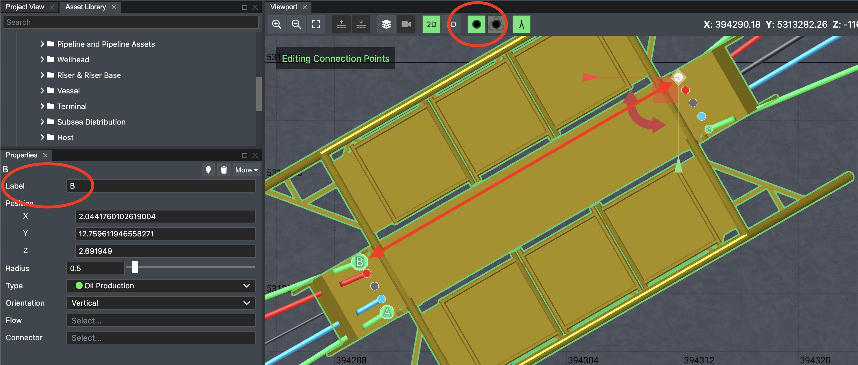
This step is only required for assets where the routing is ambiguous. In the above example, because 2 green oil production lines enter the template, and 2 leave. The other routes are known because there is only one route of each type.
Using the integration
Start by selecting the "LedaFlow" tab in the bottom row of tabs in FT Design. If it is not shown, press the Layout button and select it to show it.
The integration operates on a per-subproject basis, so the following procedure applies each time you switch project or subproject.
Flowpath search
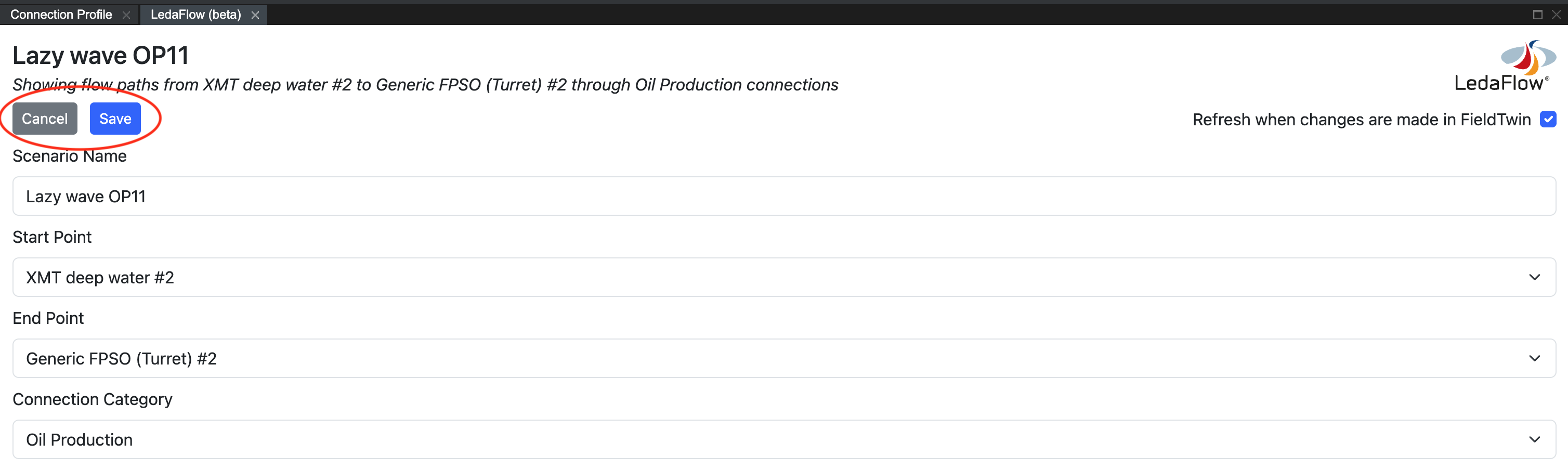
In the LedaFlow tab, select a starting point for the flow path search, optionally select an end point, and optionally limit the flow path to a particular connection type. If these options are hidden, press the Edit button below the description of the current search.
Once the values are set, press Save.
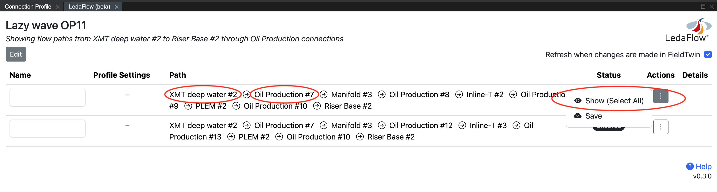
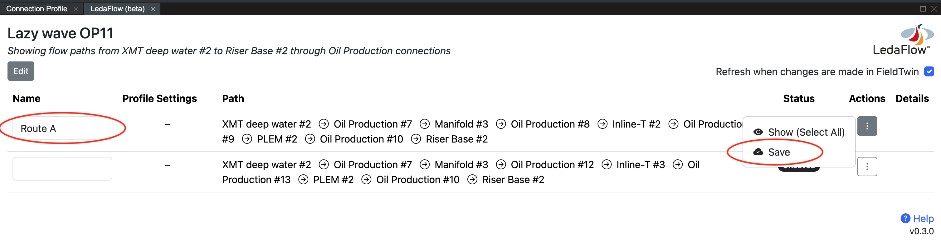
After the flow path search has completed the list of possible flow paths will be shown. Saved flow paths (if any) will be shown at the top, with unsaved flow paths listed below. To work with a flow path in LedaFlow you first need to save it.
For each flow path in the results list you can find an individual element by clicking on its name, or you can show the whole flow path by choosing Select All from the flow path's Actions menu.
Set the Refresh when changes are made checkbox if you wish to automatically update the list of possible flow paths and their statuses as you make changes to the field in FT Design.
Saving a flow path
The remaining actions in this guide require a flow path to be saved. To save a flow path, enter a name in its text box and choose Save from the flow path's Actions menu.
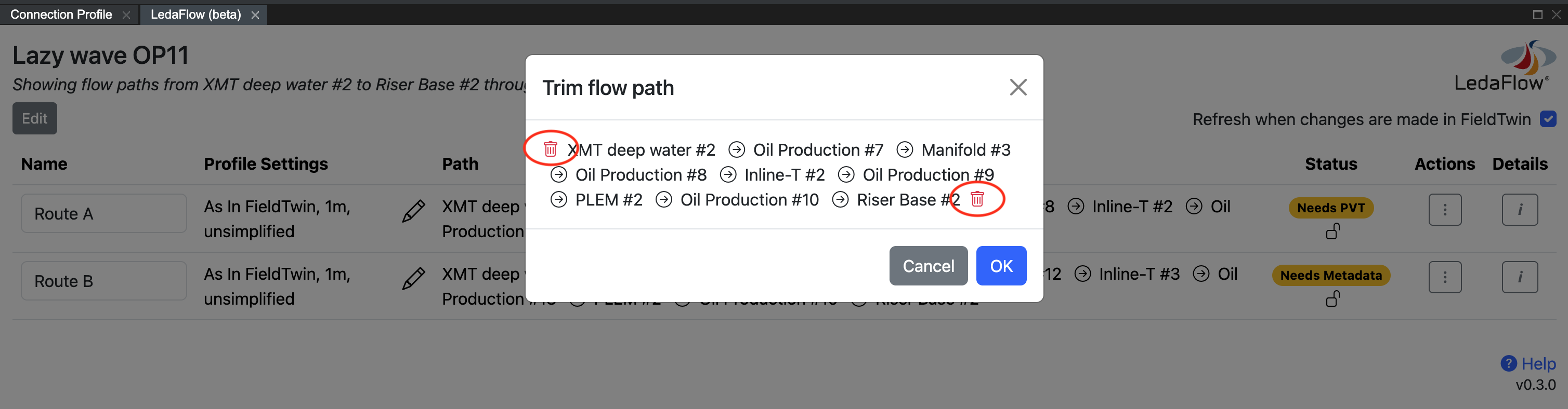
Optional - trimming a flow path
If you want to work with a portion of the whole flow path, choose Trim from the flow path's Actions menu. This will give you the ability to trim the flow path from either end. Press OK to save the trimmed path or Cancel to discard the changes.
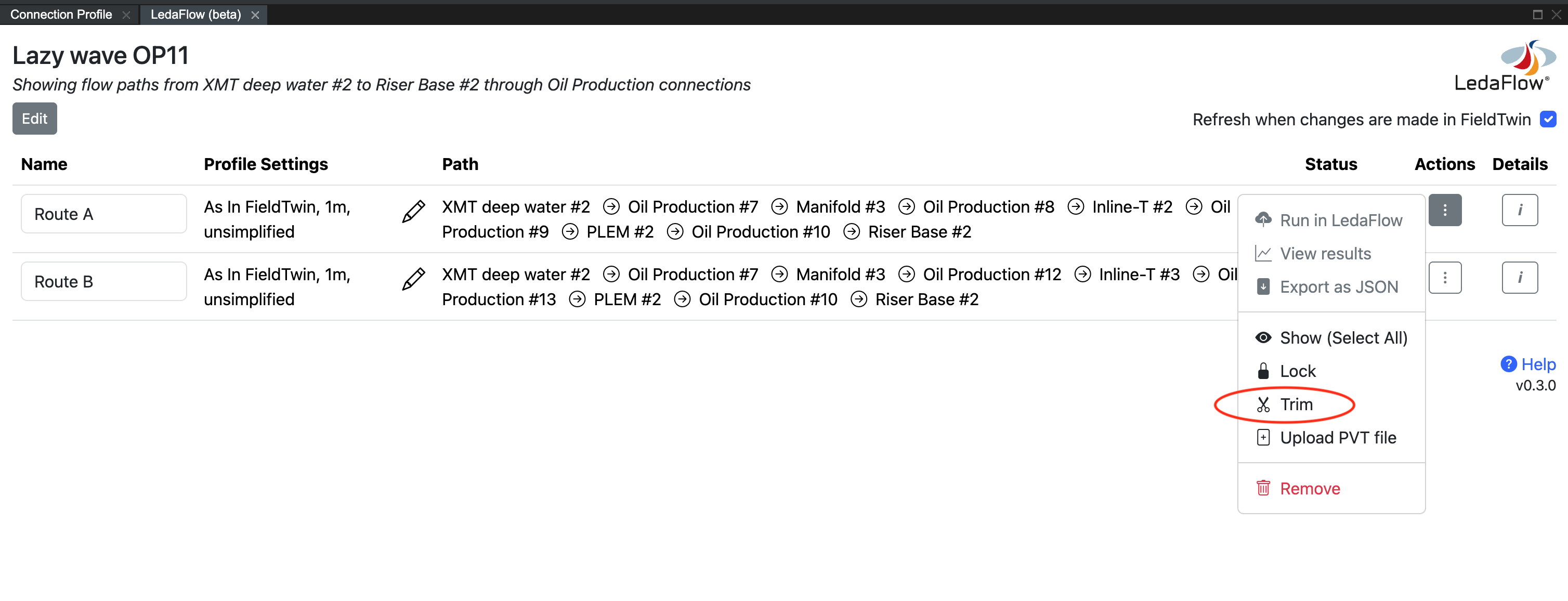
Optional - locking the items in a flow path
You can lock all of the staged assets and connections in the flow path to prevent another user from making changes to these objects while you are working. To do this, press Lock from the flow path's Actions menu. Once locked, the menu item changes to allow you to Unlock.
Setting a PVT file for a flow path
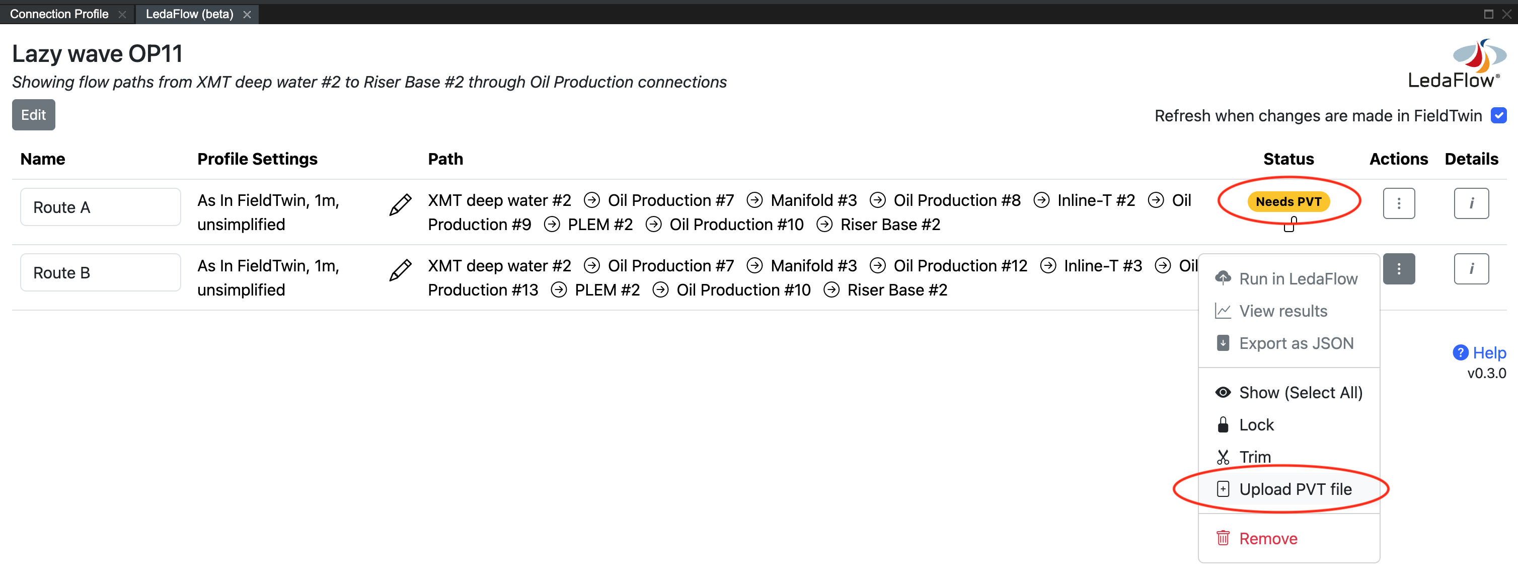
LedaFlow requires a table of Pressure Volume Temperature (PVT) data, describing the properties of the fluid, to be attached to the flow path. If this step has not yet been performed the flow path will be marked with a yellow Needs PVT status.
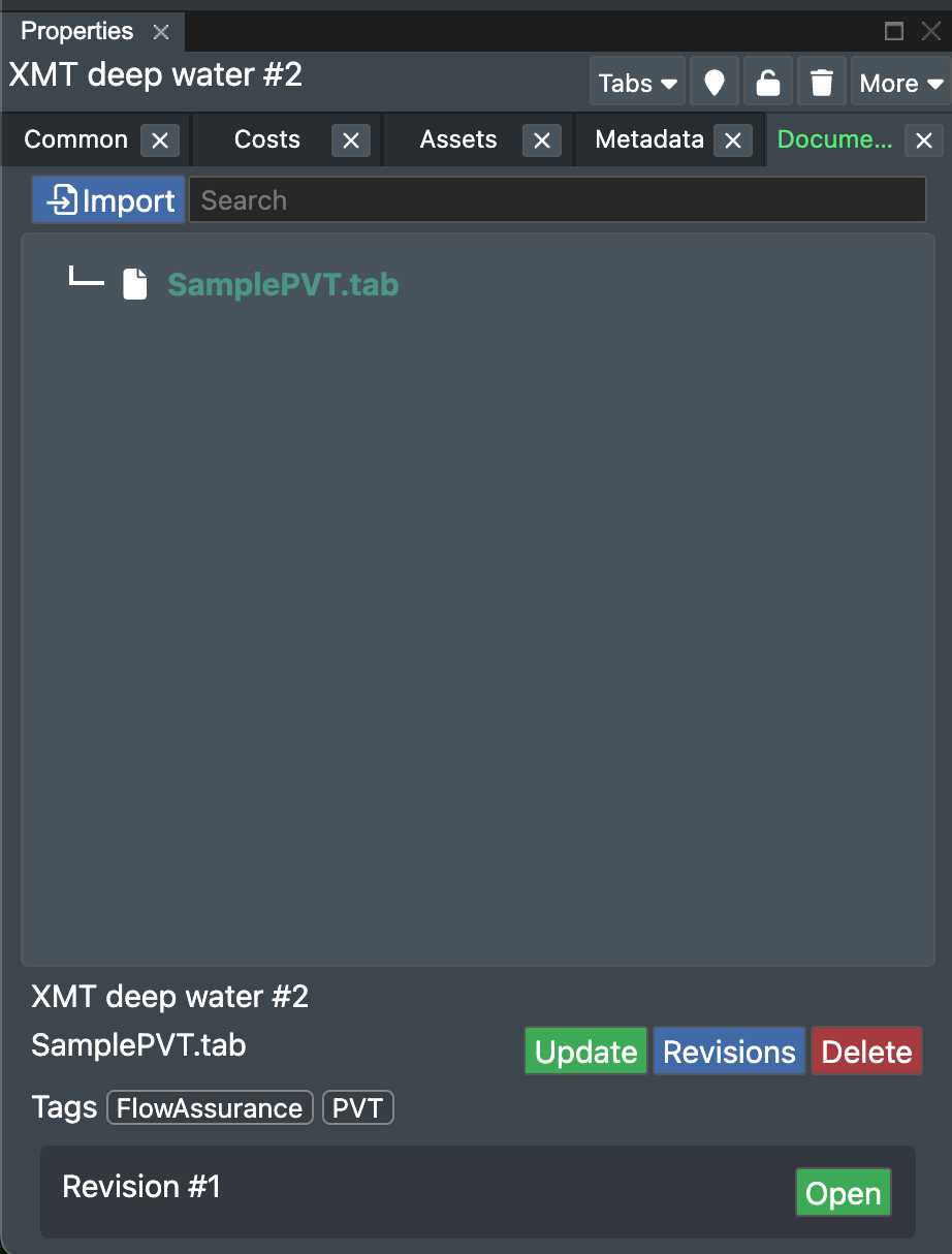
To attach PVT data, upload the PVT table as a document (in a file format that LedaFlow
supports) using the Documents tab in FT Design, and assign a tag of PVT. The
integration provides a helper function to perform these steps for you - choose
Upload PVT file from the flow path's Actions menu.
The PVT upload requires 2 steps:
- Select the object to attach the PVT file to. Typically this should be the first object in the flow path - the production tree for example - and the PVT data will then be applied to the connections that follow it. If you need to modify the fluid properties part way along a flow path, you can attach a different PVT file to a later node or connection, and this will override the earlier PVT file.
- Drag and drop or select the PVT file from your local computer.
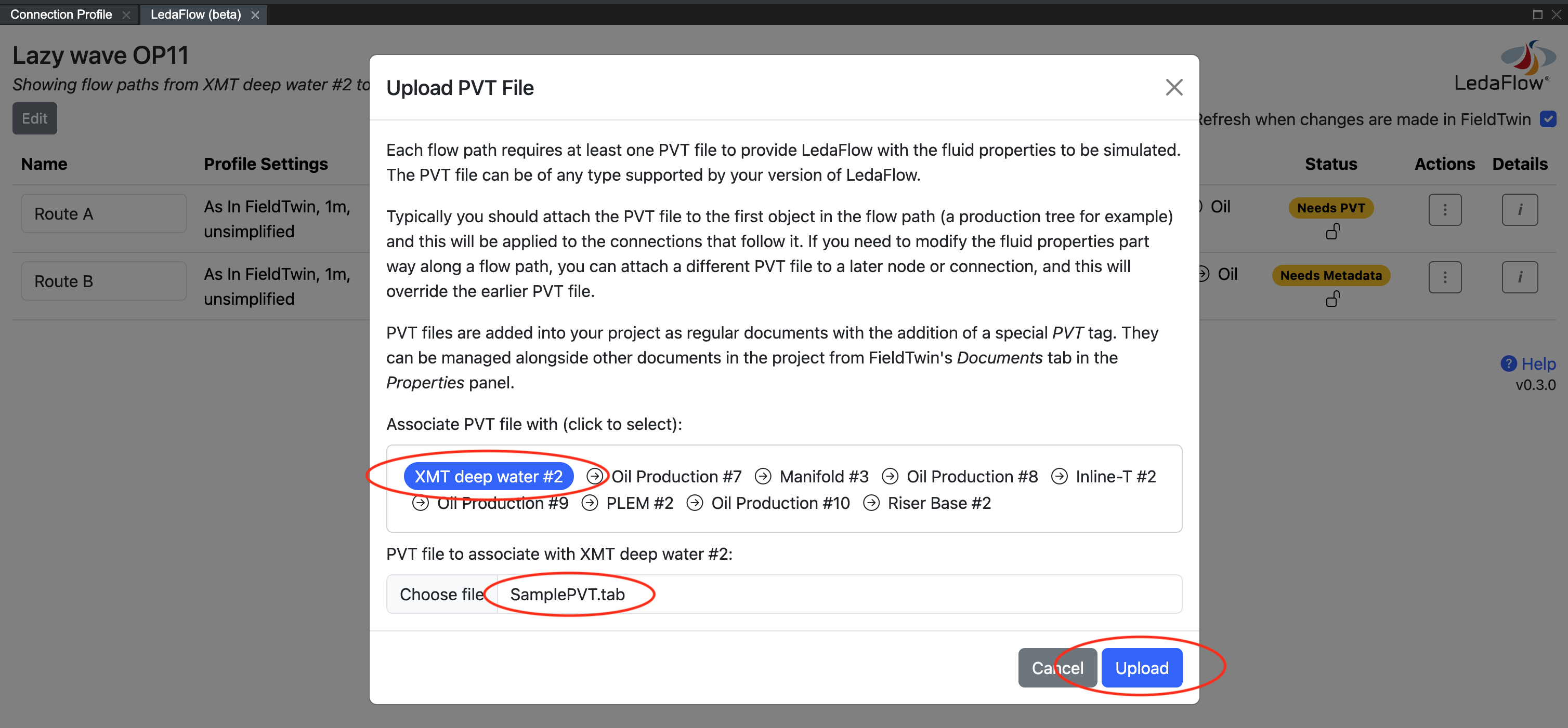
Press the Upload button to continue. The resulting PVT document can be checked, viewed, replaced and deleted as for any other uploaded document in FT Design.
Correcting flow path problems
Some saved flow paths may display a yellow or a red status message.
- Status Invalid - this indicates that the field layout has changed since the flow path was saved and the flow path now references deleted or reordered elements. Hover over the status message to view the problem. You may be able to remove a deleted element by using the Trim function, otherwise remove the invalid flow path by choosing Remove from the flow path's Actions menu. Check the list of unsaved flow paths for a replacement path that reflects the latest field layout.
- Status Missing Value - this indicates that the flow path is missing a name or a value in the export options. Hover over the status message to view the problem. A flow path must have these values set before it can be Ready.
- Status Needs Metadata - this indicates that one or more connections in the flow path is missing a required metadata value (for example roughness or inner diameter) or unit. Hover over the status message to view the problem. Correct this by clicking on the connection in the flow path to select it, then select the Metadata tab in Properties in FT Design and fill in the missing value or unit.
- Status Needs PVT - this indicates that no PVT data has been attached to the flow path. To do this, see the Setting a PVT file for a flow path section above.
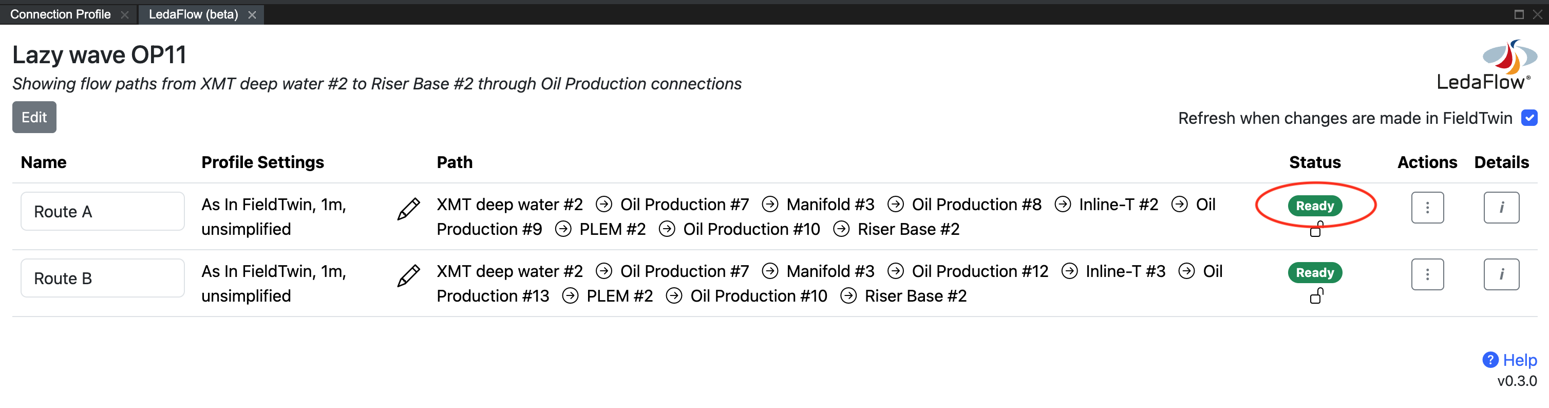
After correcting a problem, if the automatic Refresh when changes are made is not enabled, use the manual Refresh button in the integration to update the statuses of the saved flow paths.
Saved flow paths with a green Ready status can be exported to LedaFlow.
Setting the export options for a flow path
A flow path may consist of 2 distinct types of connection:
- Connections that were manually drawn or designed in FieldTwin
- For these connections FieldTwin generates a connection profile by joining up the start and end and mid points and placing the connection on top of the bathymetry layer (excluding the floating portion of a riser)
- Connections that were imported via FieldTwin's Import menu, or through the Rules Engine, or the API, or the Span Estimation Tool
- These may show a Design Type of Imported in the Properties panel
- For these connections FieldTwin can either use the imported XYZ data or it can generate a connection profile the same as above
By default, the integration provides LedaFlow with:
- A generated profile as described above for manually designed connections, with regularly spaced points (every 1 meter or 1 foot by default)
- The imported XYZ data for imported connections, where Z depends on the Connection Follows Bathymetry option that was given at import time
- No simplification of points
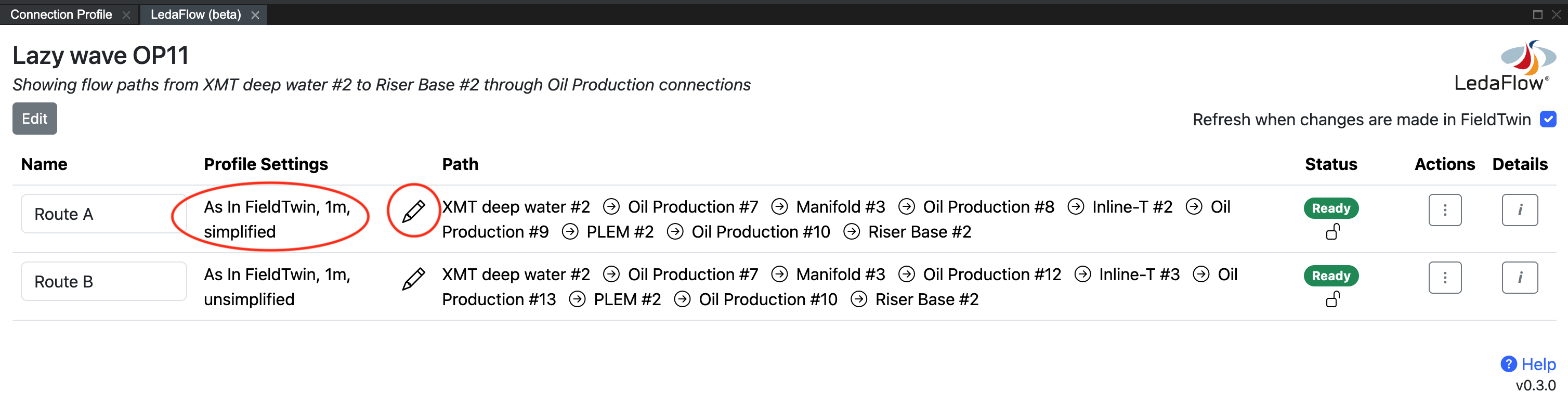
You can change these defaults by pressing the edit (pencil) icon next to a profile description in the flow paths list.
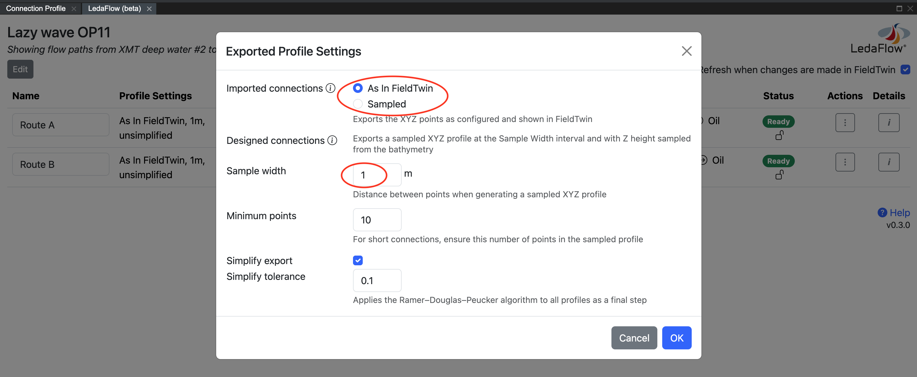
The available options for imported connections are:
| As in FieldTwin | Sampled |
|---|---|
| Uses the imported points in combination with the Connection follows bathymetry connection attribute | Generates a new profile (by interpolating the original XYZ points) using the same method and settings as for 'designed' connections |
| If the connection does not follow the bathymetry, provides the imported XYZ points unchanged | |
| If the connection does follow the bathymetry, replaces the Z component with the depth from FieldTwin's bathymetry layer |
There are no equivalent options for 'designed' connections, since only the user defined geometry points are available in FieldTwin.
The Sample Width setting controls the interval of generated points for 'designed' connections
and for the Sampled option. The lower the value (minimum 1) the more points and the higher
the resolution of the flow path profile that is made available to LedaFlow.
Depending on the value of Sample Width it is possible that short connections would be exported with a very small number of points. The Minimum Points setting ensures a minimum number of points in the exported profile [* see below], overriding Sample Width when required.
You can optionally simplify the exported profiles to reduce the number of points by
removing points that fall in a straight line. This function uses the
Ramer–Douglas–Peucker algorithm
when enabled. The lower the tolerance (minimum 0.01) the fewer points are removed.
Simplification applies to all profile types for both 'designed' and imported connections.
* As simplification happens last it is possible that a simplified profile will contain fewer points than the Minimum Points setting.
Press OK to save your changes or Cancel to discard them.
Viewing the final profile types
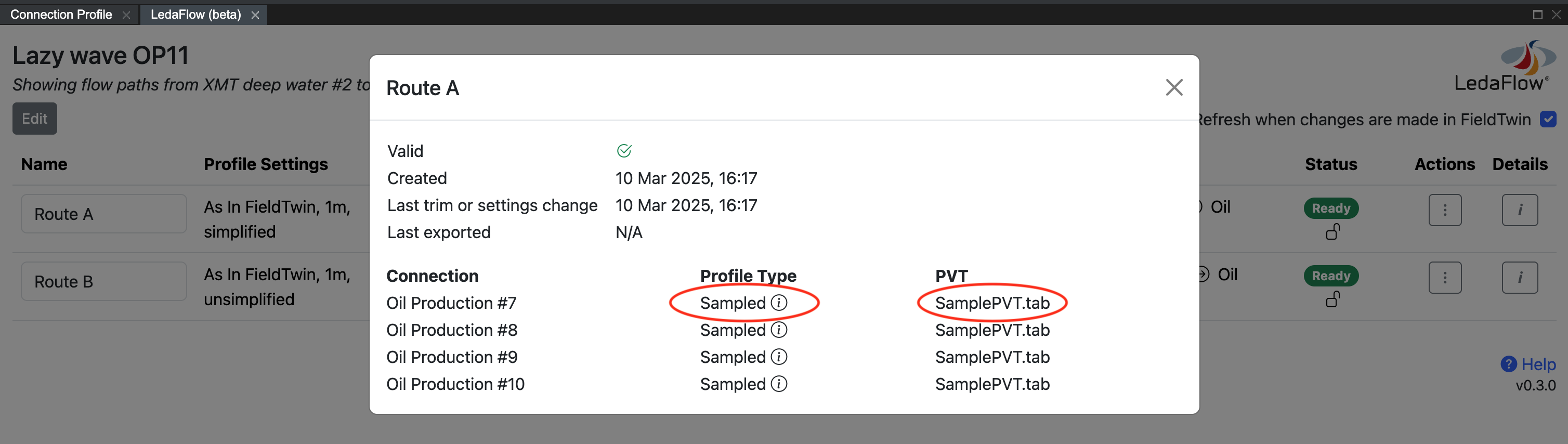
To see the list of connections in a flow path and what type of profile and what PVT file will apply to each, return to the main flow path list and click the flow path's Details button. In the list of connections you can hover over the "i" icon to see the reason why that profile type applies.
Running a flow path simulation in LedaFlow (Desktop)
FieldTwin cannot communicate directly with the LedaFlow desktop application, but you can export the flow path data in JSON format and import this file into LedaFlow.
Choose Export as JSON from the flow path's Actions menu.
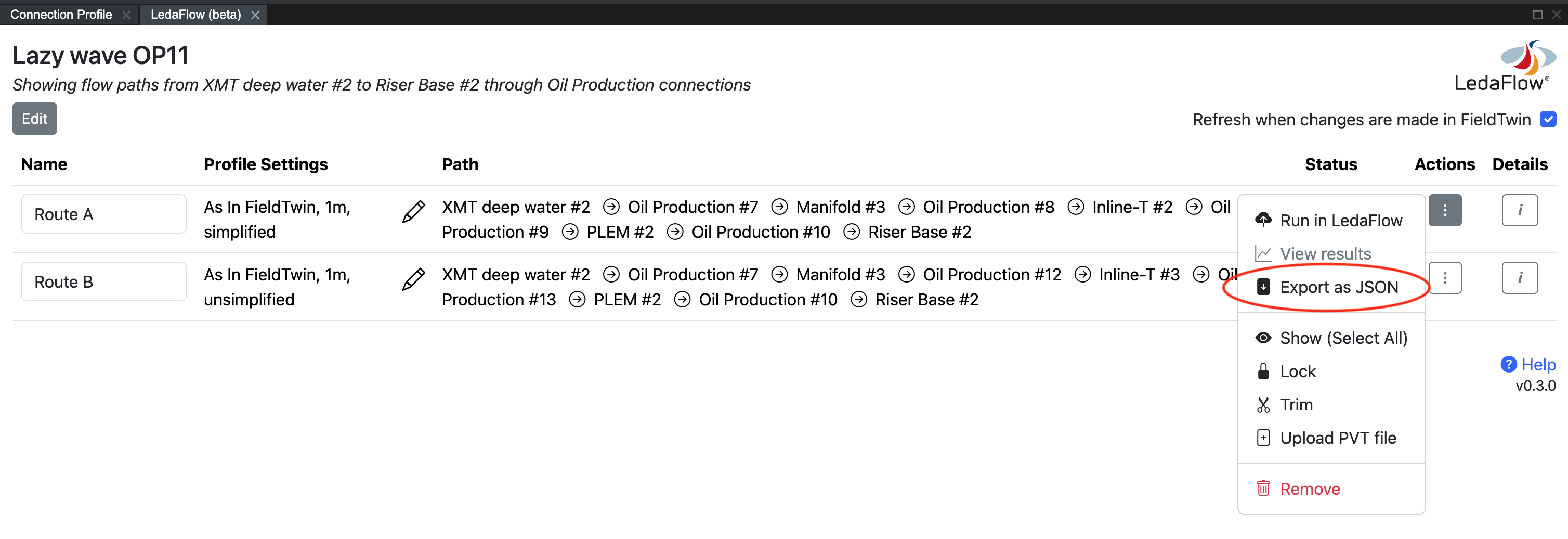
A data file will be downloaded to your local computer. After importing this file into LedaFlow you can run simulations there. Any results that you wish to store in FieldTwin will need to be manually uploaded as FieldTwin documents.
Running a flow path simulation in LedaFlow (Cloud)
For cloud-enabled editions of LedaFlow, the integration can run a simulation and display the results without leaving FT Design. Choose Run in LedaFlow from the flow path's Actions menu.
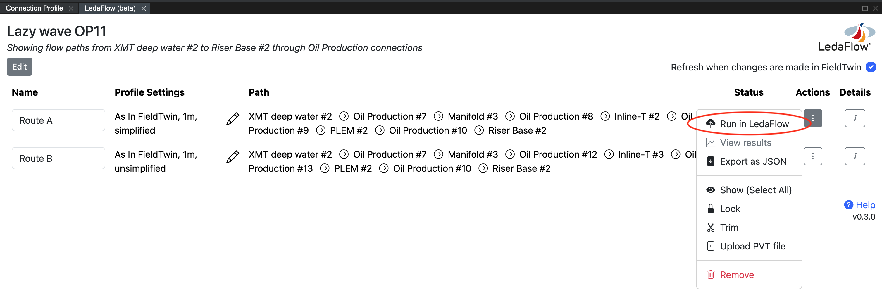
Select the LedaFlow function to run, enter the parameters for the selected function, and press the Run button. A simulation may take between several seconds and several minutes to complete.
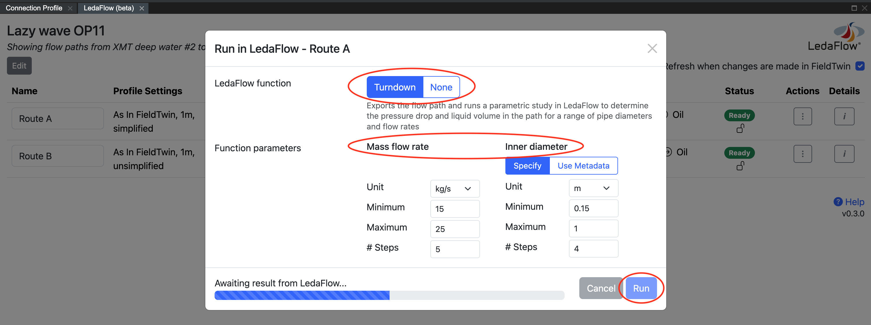
The available functions are:
| Function | Description | Parameter |
|---|---|---|
| Turndown | Exports the flow path and runs a parametric study in LedaFlow to determine the pressure drop and liquid volume in the path for a range of pipe diameters and flow rates | Mass flow rates - a range of flow rates (2 or more), each of which will be simulated |
| Inner diameters (specified) - a range of inner diameters (1 or more), each of which will be simulated. Assumes the same diameter for all connections and ignores the FieldTwin metadata value for inner diameter. | ||
| Inner diameter (use metadata) - uses the FieldTwin metadata value for inner diameter as the diameter of each connection. Connections may have different diameters. | ||
| None | Exports the flow path to create a new "case" in LedaFlow, does not run any simulation | None |
Upon completion of the simulation, a results page will be displayed. The results content is dependent on the function but for Turndown it includes a connection selection (there is one chart for each connection in the flow path) and the ability to show or hide the result for each inner diameter that was simulated.
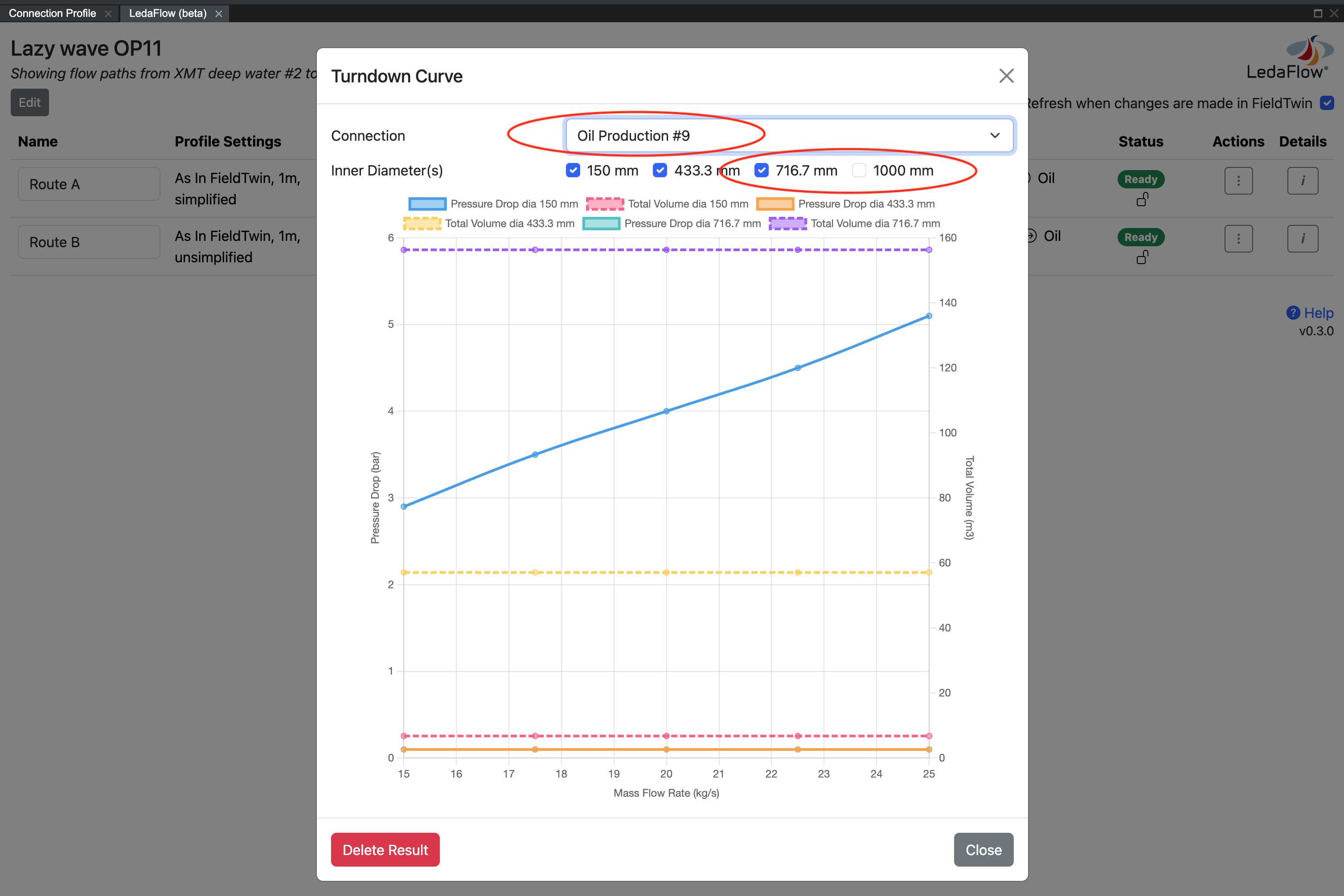
If the result should not be kept, press the Delete Result button and confirm the choice to permanently delete it.
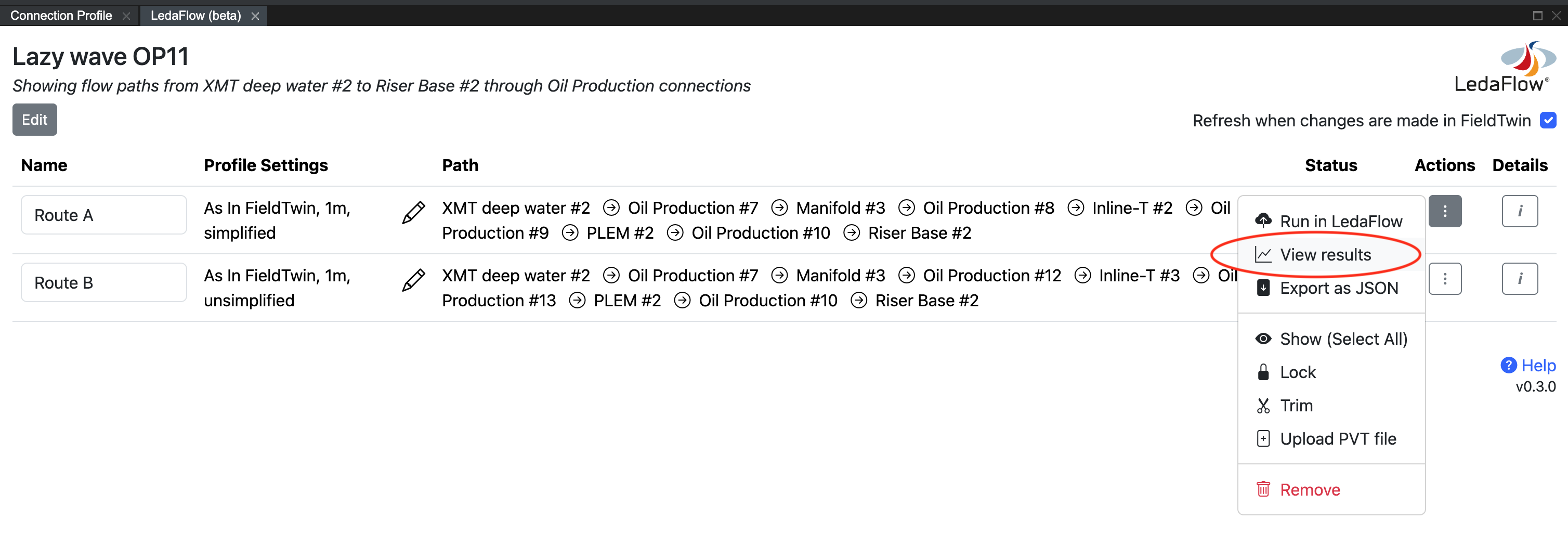
Viewing or deleting a previous result
The last result of each type is recorded by the integration so that it can be viewed again at a later time. Older results are not shown because the integration has no way of knowing if past results are still valid, for example a pipeline might have since been re-routed. To see the list of results available, choose View results from the flow path's Actions menu.
Then press the View button next to the result to view. This will reload the result data and redisplay it as before.
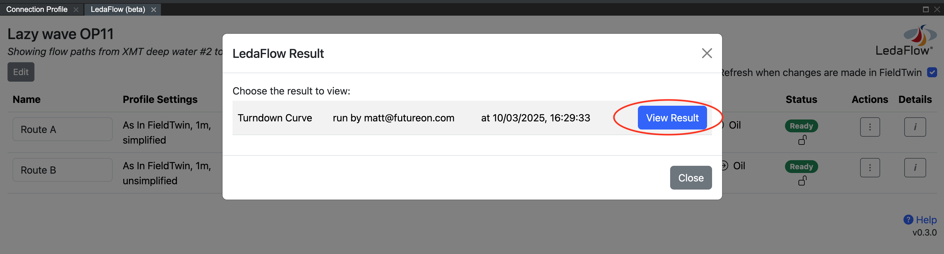
If the result is not wanted, press the Delete Result button and confirm the choice to permanently delete it.
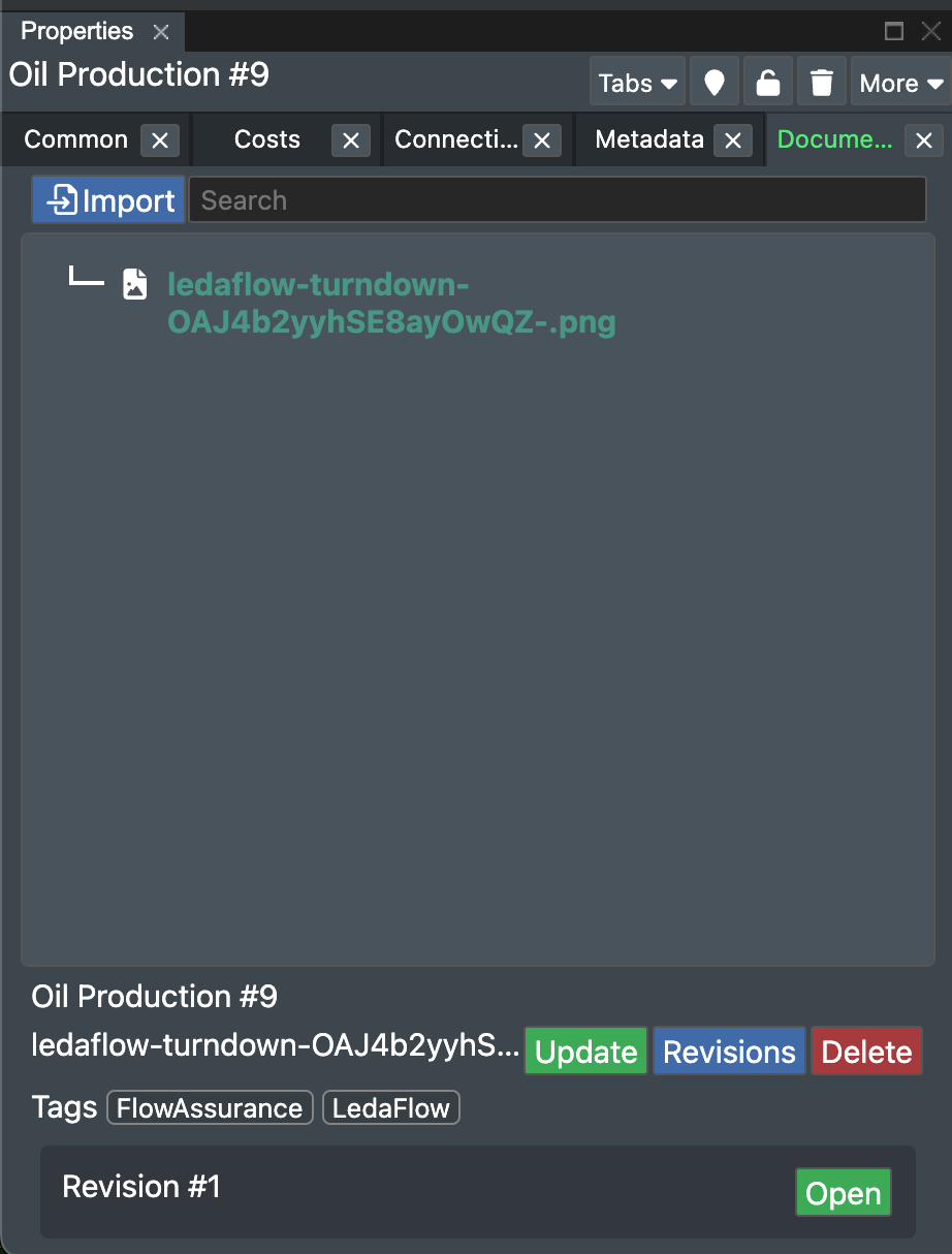
The result of each function, for each connection, is stored as a document in FieldTwin similar to the way the PVT file is stored. A result document can be checked, viewed, replaced and deleted as for any other uploaded document in FT Design. If the same LedaFlow function is run again for the same connection, this will create a new document revision.
Unsaving a flow path
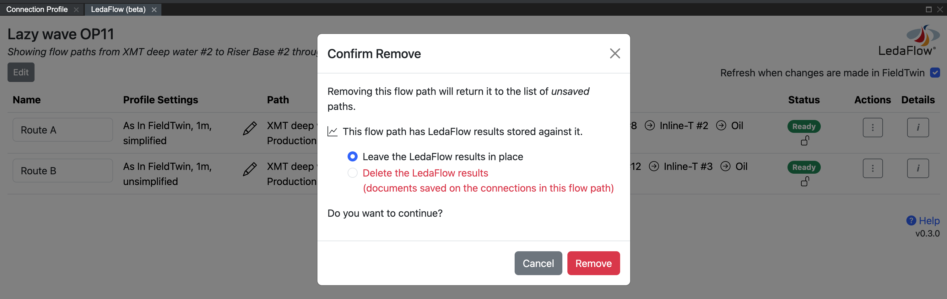
To remove a flow path from the list of saved flow paths, choose Remove from the flow path's Actions menu.
None of the staged assets or connections in the project are affected by this action.
If a simulation has been run you will be given the option of whether to delete the stored results files or leave them in place. If you leave the results in place you will be able to access them as static files from the Documents tab on each connection in FT Design. It will no longer be possible to browse these results from the integration.
After removal, if the removed flow path matches the current search criteria it will reappear in the list of available unsaved flow paths.